Transformer protection current break variable starting method and transformer protection device

A current mutation and transformer protection technology, applied in emergency protection circuit devices, electrical components, etc., can solve the problems of discrimination failure and failure to guarantee the reliability of discrimination, and achieve the effect of reliable start-up

Active Publication Date: 2020-02-07
河南许继继保电气自动化有限公司 +3
View PDF5 Cites 3 Cited by
  • Summary
  • Abstract
  • Description
  • Claims
  • Application Information

AI Technical Summary

Problems solved by technology

[0003] The purpose of the present invention is to provide a method for starting a sudden change in current for transformer protection and a transformer protection device, which are used to solve the proble

Method used


Image

  • Transformer protection current break variable starting method and transformer protection device
  • Transformer protection current break variable starting method and transformer protection device
  • Transformer protection current break variable starting method and transformer protection device

Examples


Embodiment 1

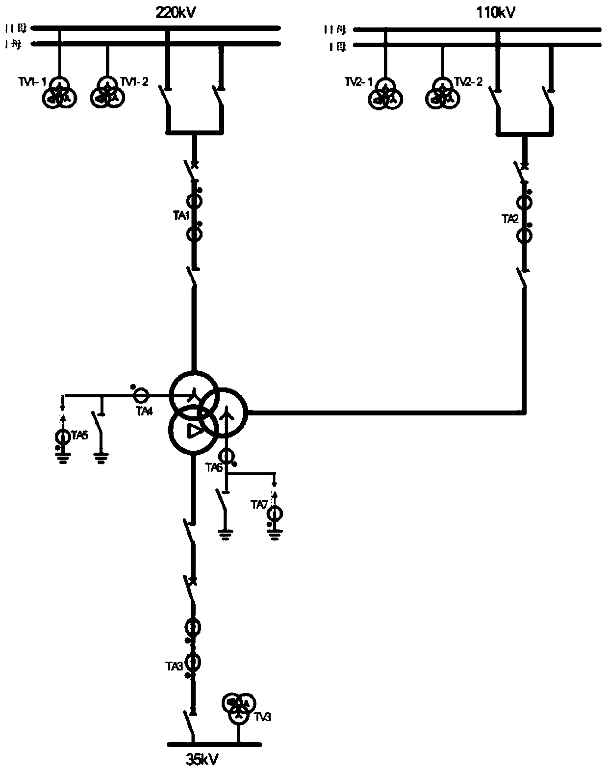
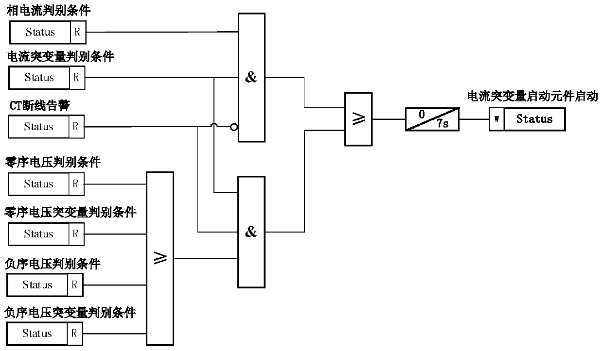
[0030] The current mutation start method for transformer protection of the present invention is mainly used in the local transformer protection device of the smart grid. On the basis of the existing judgment on the current mutation, by increasing the zero sequence Sequence voltage, zero-sequence voltage mutation or negative-sequence voltage mutation is judged, and compared with the set voltage threshold, to determine whether to control the current mutation of the transformer protection to start the element, to prevent the current sensor on one side of the transformer When a disconnection fault occurs, the starting element will refuse to move due to the sudden change in current, so as to improve the reliability of the transformer protection device. The specific embodiments of the present invention will be further described below in conjunction with the accompanying drawings.

[0031] figure 1 In the main wiring mode of the 220kV transformer shown, the transformer protection de...

Embodiment 2

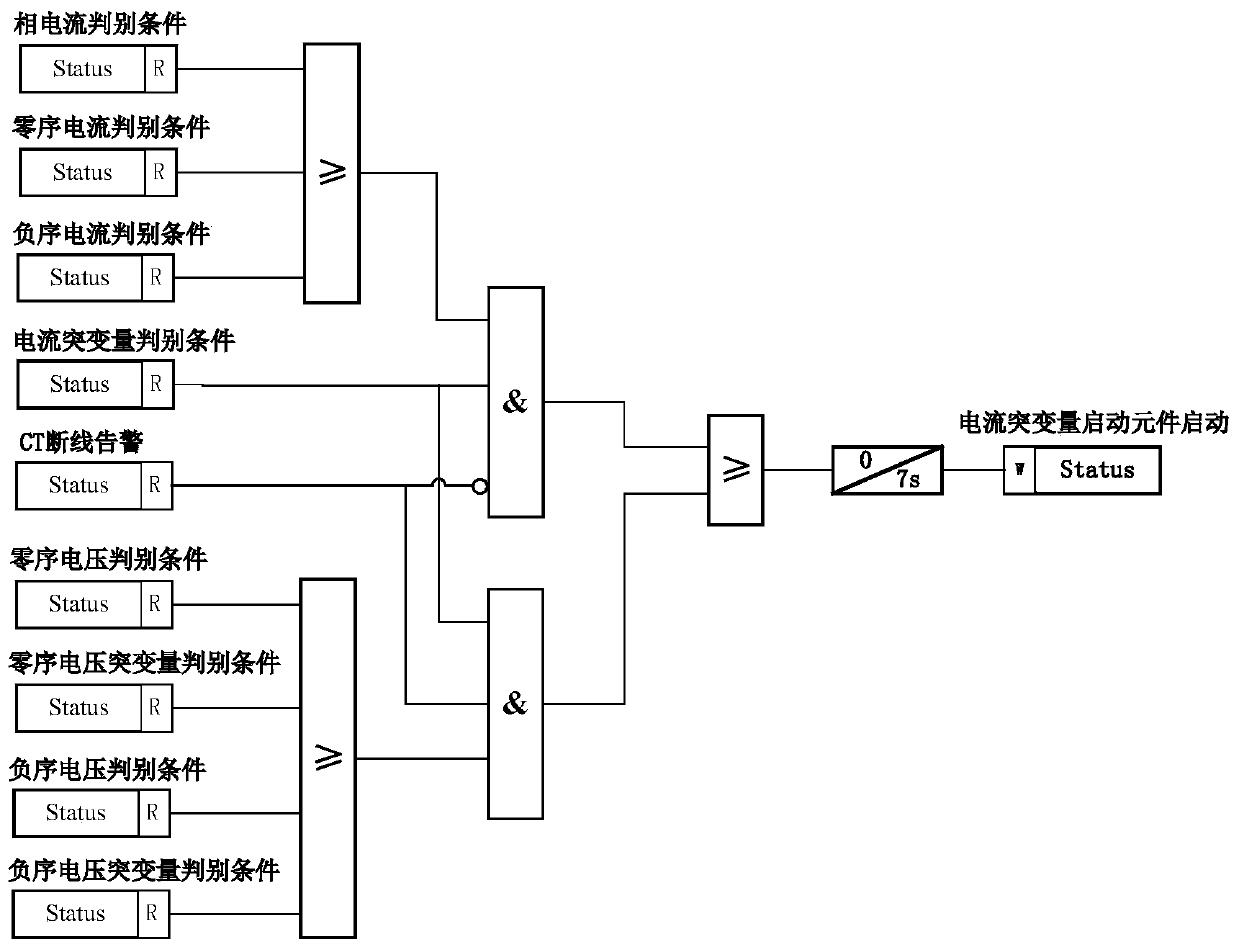
[0052] In order to judge whether the current sudden change starting element is activated, the current sudden change starting method of this embodiment is the same as the method embodiment 1, and both include three criteria, namely criterion one, criterion two and criterion three, and the start method logical as image 3 As shown, criterion 1 and criterion 3 are the same as those described in method embodiment 1, the difference is that zero-sequence current and negative-sequence current start-up criteria are added in criterion 2, therefore, there is phase current at the corresponding side of the transformer Or zero-sequence current or negative-sequence current starting to meet the discriminant equation is:

[0053]

[0054] The above formulas correspond to phase current discrimination conditions, zero-sequence current discrimination conditions and negative-sequence current discrimination conditions in turn. In the above formula, I Φ1.MAX (t) is the maximum phase current amp...


PUM


Abstract

The invention relates to a transformer protection current break variable starting method and a transformer protection device. The method comprises the steps of: carrying out the determination of a current break variable of a transformer and the zero-sequence voltage, the negative-sequence voltage, the zero-sequence voltage break variable and the negative-sequence voltage break variable of the corresponding side of the transformer when a current sensor at one side of the transformer has a disconnection fault; when the current break variable of a certain phase of the high-voltage side or the medium-voltage side of the transformer is larger than a current break variable threshold value and the zero-sequence voltage, the negative-sequence voltage, the zero-sequence voltage break variable or the negative-sequence voltage break variable of the corresponding side of the transformer is larger than a voltage threshold value, controlling a starting element to be started; and when the current break variable of a certain phase at the low-voltage side of the transformer is greater than the current break variable threshold value and the negative-sequence voltage or the negative-sequence voltagebreak variable at the corresponding side of the transformer is greater than the voltage threshold value, controlling the starting element to start. According to the invention, even if the current sensor on one side of the transformer has a disconnection fault, the current break variable starting element can still be reliably started.

Description

technical field [0001] The invention belongs to the technical field of electric power system relay protection, and in particular relates to a method for starting a sudden change in current for transformer protection and a transformer protection device. Background technique [0002] In the prior art, the current sudden change start element detects the change of each phase current in real time through an effective current sensor to judge whether the protected equipment is faulty. The main initiating element of protection. However, the above-mentioned method of real-time detection of current changes in each phase is applicable to the situation that the current sensor on either side of the transformer does not have a disconnection fault. , the reliability of the discrimination cannot be guaranteed. Contents of the invention [0003] The object of the present invention is to provide a method for starting a sudden change in current for transformer protection and a transformer ...

Claims


Application Information

Patent Timeline
IPC IPC(8): H02H7/04
CPCH02H7/04
Inventor 邓茂军马和科李宝伟倪传坤樊占峰王智勇李旭李文正陈继瑞吕利娟
Owner 河南许继继保电气自动化有限公司
Why Eureka
Try Eureka