
Dough splitting device

A technology for dividing dough and dough, which is applied in the fields of dough cutting machinery, baking, food science, etc., can solve the problems of high maintenance cost, difference in dough quantity, high cost, etc., and achieves low structural precision requirements, low cost, and suitable for wide range of effects

Inactive Publication Date: 2020-02-11
宿州麦香缘食品有限公司
View PDF7 Cites 1 Cited by
  • Summary
  • Abstract
  • Description
  • Claims
  • Application Information

AI Technical Summary

Problems solved by technology

[0002] In the processing technology of noodle food, it is necessary to divide the dough equally. Most of the dividing mechanisms ensure that the dough is discharged at a uniform speed, and then the dough is cut in equal amounts by controlling the cutting interval. The same amount of dough is cut at intervals. When the dough output speed changes, the amount of dough is likely to have a large difference.
[0003] Therefore, a new device using sensors is proposed to sense the passage of the dough, such as the patent document CN201120496645.0, which discloses a dough quantitative dividing machine, and an upper cover sensor switch is arranged above the hollow hopper 11 13. There is a front cover sensor switch 41 at the edge relative to the front cover 20, and then the cutting device 100 completes the cutting of the extruded material, but the equivalent division effect of this device is not satisfactory, and the sensor can only sense It is impossible to sense the amount of dough passing through. If the amount of dough passing through the sensor changes, the cut dough will not be equal. Moreover, the machine using the sensor is expensive and the maintenance cost is high.

Method used


Image

  • Dough splitting device
  • Dough splitting device
  • Dough splitting device

Examples


Embodiment 1

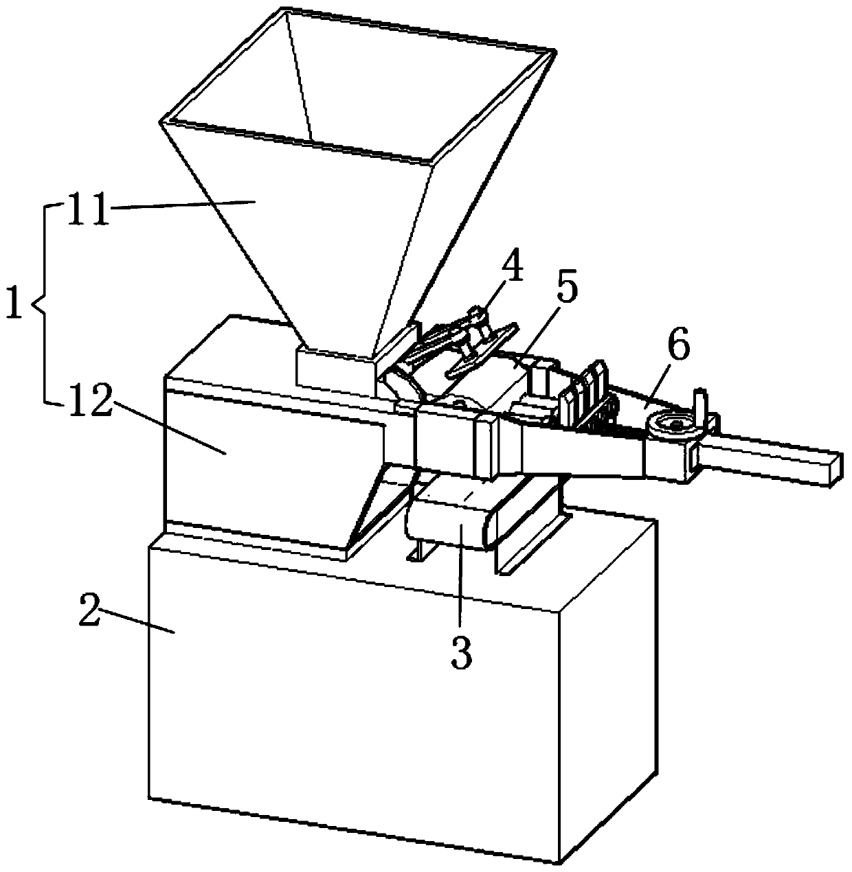
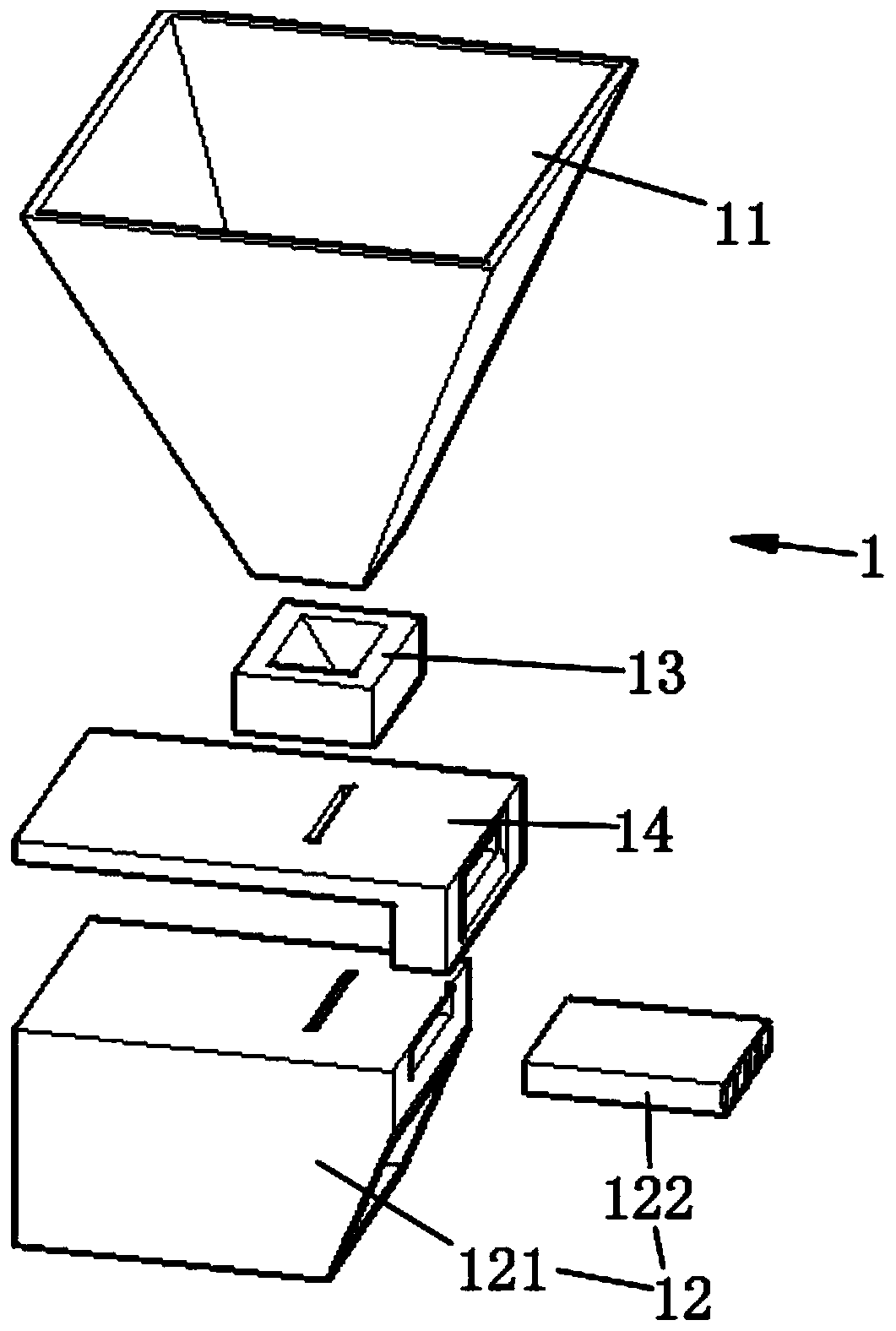
[0042] refer to figure 1 , this embodiment discloses a dough grouping device, including a feeding device 1 , a base 2 , a conveying device 3 and a grouping mechanism 5 . The feeding device 1 is installed on a base 2 . The grouping mechanism 5 is rotatably connected to the feeding device 1 . The conveying device 3 is arranged below the group separating mechanism 5 .

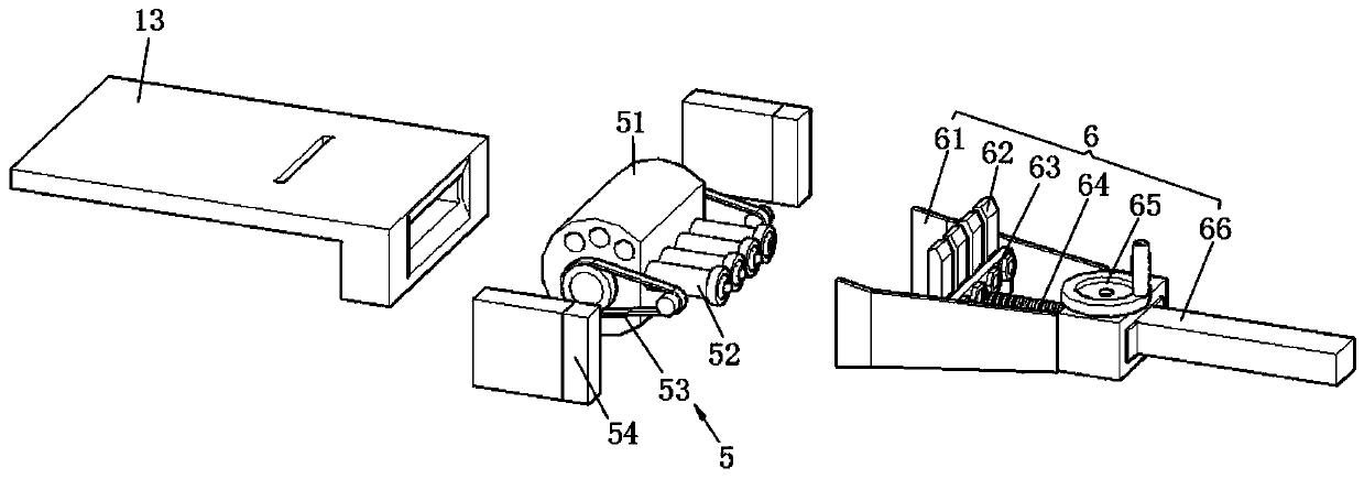
[0043] The grouping mechanism 5 includes a grouping cylinder 51 rotating along its axis, a movable column 52 and a cylindrical through hole 55 . Cylindrical through-holes 55 run side by side on the curved surface of the grouping cylinder 51 . A movable post 52 is inserted into a port of the cylindrical through hole 55 . When the cylindrical through hole 55 is aligned with the feeding port of the feeding device 1 , the dough is fed into the cylindrical through hole 55 from the feeding device 1 , and the movable column 52 is squeezed outward from the cylindrical through hole 55 . When the cylindrical through ho...


PUM


Abstract

The invention discloses a dough splitting device, which includes a feeding device, a base, a conveying device and a dough splitting mechanism; the feeding device is installed on the base; the dough splitting mechanism is rotationally connected with the feeding device; the conveying device is arranged below the dough splitting mechanism; the dough splitting mechanism includes a dough splitting cylinder rotating along the axis of the dough splitting mechanism, movable columns and cylindrical through-holes; the cylindrical through-holes are arranged side by side in the curved surface of the doughsplitting cylinder; the movable columns are inserted in one ports of the cylindrical through-holes; and when the cylindrical through-holes are aligned with the feeding opening of the feeding device,dough is fed into the cylindrical through-holes from the feeding device, the movable columns are extruded outwards from the cylindrical through-holes, and when the cylindrical through-holes directly face the conveying device, under the action of gravity, the movable columns press the dough in the cylindrical through-holes to the conveying device. The invention has the advantages of equal weight ofsplitted dough, low equipment cost and wide application range.

Description

technical field [0001] The invention relates to the technical field of dough division, in particular to a dough division equipment. Background technique [0002] In the processing technology of noodle food, it is necessary to divide the dough equally. Most of the dividing mechanisms ensure that the dough is discharged at a uniform speed, and then the dough is cut in equal amounts by controlling the cutting interval. The same amount of dough is cut at intervals. When the dough output speed changes, the amount of dough is likely to have a large difference. [0003] Therefore, a new device using sensors is proposed to sense the passage of the dough, such as the patent document CN201120496645.0, which discloses a dough quantitative dividing machine, and an upper cover sensor switch is arranged above the hollow hopper 11 13. There is a front cover sensor switch 41 at the edge relative to the front cover 20, and then the cutting device 100 completes the cutting of the extruded ma...

Claims


Application Information

Patent Timeline
Patent Type & Authority Applications(China)
IPC IPC(8): A21C5/02
CPCA21C5/02
Inventor 张承美
Owner 宿州麦香缘食品有限公司
Learn More