Stirring kettle for producing winding adhesive, and stirring method thereof

A stirring method and a stirring tank technology, which are applied in the direction of mixing methods, mixer accessories, chemical instruments and methods, etc., can solve the problems of unsuitability for large-scale production requirements, inconvenient portability, low stirring efficiency of the stirring tank, etc., and achieve simple structure , improve stirring efficiency, and facilitate operation

Inactive Publication Date: 2020-02-11
衡阳开拓光电科技有限公司
View PDF9 Cites 0 Cited by
  • Summary
  • Abstract
  • Description
  • Claims
  • Application Information

AI Technical Summary

Problems solved by technology

The main indicator of the fiber optic gyroscope is ring body crosstalk. According to the actual application of the ring rubber, it is found that the stirring tank used in the production of the ring rubber

Method used


Image

  • Stirring kettle for producing winding adhesive, and stirring method thereof
  • Stirring kettle for producing winding adhesive, and stirring method thereof
  • Stirring kettle for producing winding adhesive, and stirring method thereof

Examples


Example Embodiment

[0042] Example 1

[0043] A method for stirring a stirred tank for production of ring-wound rubber, comprising the following steps:

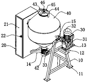
[0044] Step 1. Place the stirred tank at a suitable position, control the rotation of the motor a30 through the switch group 23, and adjust the reducer 31 so that the tank body 40 can be tilted to an angle that is convenient for feeding;

[0045] Step 2, by rotating the dovetail bolt 46, the kettle cover 44 is separated from the top opening of the kettle body 40, and feeding is carried out;

[0046] Step 3: after feeding, fix the kettle cover 44 to completely seal the kettle body 40, and control the rotation of the motor a30 through the switch group 23, so that the whole kettle body 40 is turned over and stirred;

[0047] Step 4. After the stirring is finished, control the opening of the kettle body 40 to tilt downward, open the kettle cover 44 and add it to the fiber-coated glue tank through a glass straw.

[0048] In the embodiment, specifical...

Example Embodiment

[0058] Experimental example 3

[0059] A method for stirring a stirred tank for production of ring-wound rubber, comprising the following steps:

[0060] Step 1. Place the stirred tank at a suitable position, control the rotation of the motor a30 through the switch group 23, and adjust the reducer 31 so that the tank body 40 can be tilted to an angle that is convenient for feeding;

[0061] Step 2, by rotating the dovetail bolt 46, the kettle cover 44 is separated from the top opening of the kettle body 40, and feeding is carried out;

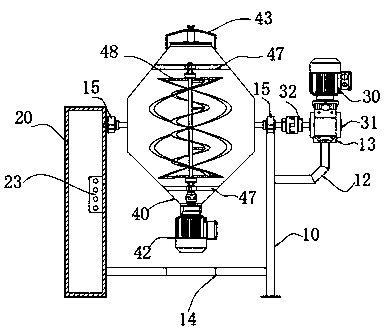
[0062] Step 3: After feeding, fix the kettle cover 44 to completely seal the kettle body 40, and simultaneously control the rotation of the motor a30 and the motor b42 through the switch group 23, and turn over and stir the kettle body 40;

[0063] Step 4. After the stirring is finished, control the opening of the kettle body 40 to tilt downward, open the kettle cover 44 and add it to the fiber-coated glue tank through a glass straw.

[0064]...


PUM


Abstract

The invention discloses a stirring kettle for producing a winding adhesive, and a stirring method thereof. The stirring kettle comprises: a trapezoidal support, wherein one side of the bottom of the trapezoidal support is connected with the bottom of a cabinet body through a K-shaped cross rod, bearing seats with the same specification and size are fixedly mounted at the top of the trapezoidal support and one side surface of the cabinet body, and bearings are arranged in the bearing seats; and a kettle body, wherein the kettle body is a biconical kettle body, and the middle parts of two sidesof the kettle body are fixedly connected with the inner rings of the bearings in the bearing seats through rotating shafts. The rotation of a motor a is controlled through a switch group to achieve overturning mixed stirring of the whole kettle body, and a motor b is controlled to rotate to make the motor b drive a stirring rod, a stirring blade a and a stirring blade b on a stirring assembly to stir raw materials, or the motor a and the motor b are controlled to rotate to overturn and stir the kettle body, so the stirring efficiency is improved.

Description

technical field [0001] The invention relates to the technical field of ring rubber production, in particular to a stirring tank for ring rubber production and a stirring method thereof. Background technique [0002] During the winding process of the fiber optic gyroscope, the optical fiber needs to be coated with a special ultraviolet glue, and then wound on the ring body. In order to ensure the use performance, the ultraviolet glue should not be exposed to light as much as possible before the loop. During the looping process, the ultraviolet glue solution is added to the fiber-coating glue tank with a glass straw, and the glue is applied when the optical fiber passes through the glue tank. The main indicator of the fiber optic gyroscope is ring body crosstalk. According to the actual application of the ring rubber, it is found that the stirring tank used in the production of the ring rubber has low stirring efficiency, is not suitable for large-scale production requirements...

Claims


Application Information

Patent Timeline
IPC IPC(8): B01F9/08B01F3/08B01F3/10B01F15/06B01F29/64B01F23/47
CPCB01F23/405B01F23/43B01F23/47B01F29/64B01F35/93B01F2101/36
Inventor 沈林姜波
Owner 衡阳开拓光电科技有限公司
Why Eureka
Try Eureka