Clamping device with pressure sensor

A technology of pressure sensor and clamping device, which is applied in the direction of workpiece clamping device, manufacturing tools, etc., can solve problems such as troublesome, inconvenient, and difficult operation

Inactive Publication Date: 2020-02-11
湖南绚丽新材料科技有限公司
View PDF7 Cites 27 Cited by
  • Summary
  • Abstract
  • Description
  • Claims
  • Application Information

AI Technical Summary

Problems solved by technology

[0002] In automation equipment, the clamping device is the most common equipment, which is used for loading and unloading products or parts in production; due to the clamping of products or parts, the splint needs to exert force on the parts or products; but this clamping force It is difficult to control. If the clamping force is too large, the product clamp will be deformed and affect the product quality; if the clamping force is too small, the product will fall during the clamping process due to lack of clamping force, causing product damage; existing In technology, in order to accurately control the clamping force of the splint on the product, a clamping force control component is often installed on the splint; however, adding a clamping force control component to the splint requires increasing the size of the splint or changing the shape of the splint. more troublesome and inconvenient
[0003] Chinese patent (notification number: CN207841138U) discloses a clamping device with a pressure sensor, including a controller, a servo motor electrically connected to the controller,

Method used


Image

  • Clamping device with pressure sensor
  • Clamping device with pressure sensor
  • Clamping device with pressure sensor

Examples


Embodiment 1

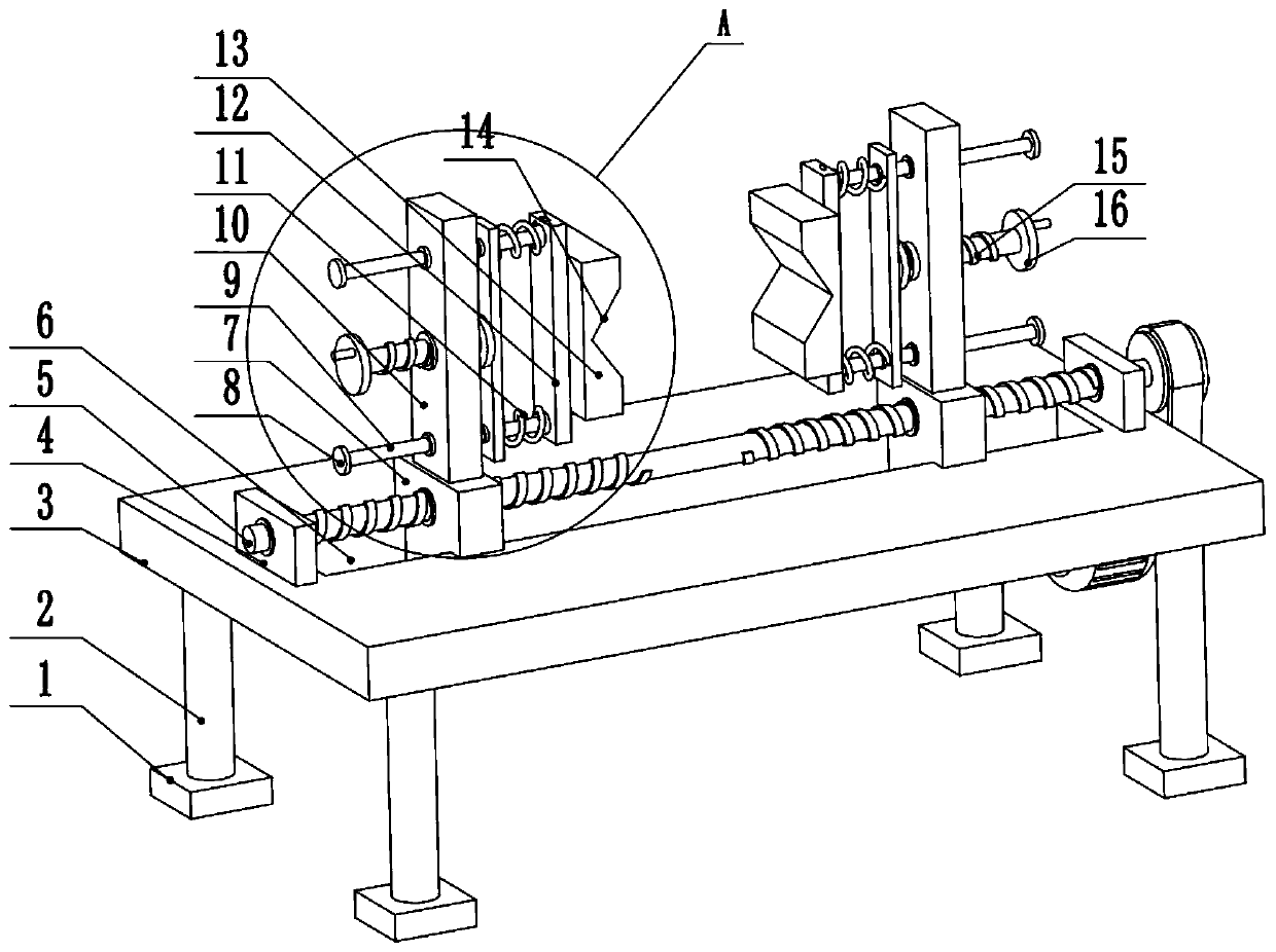
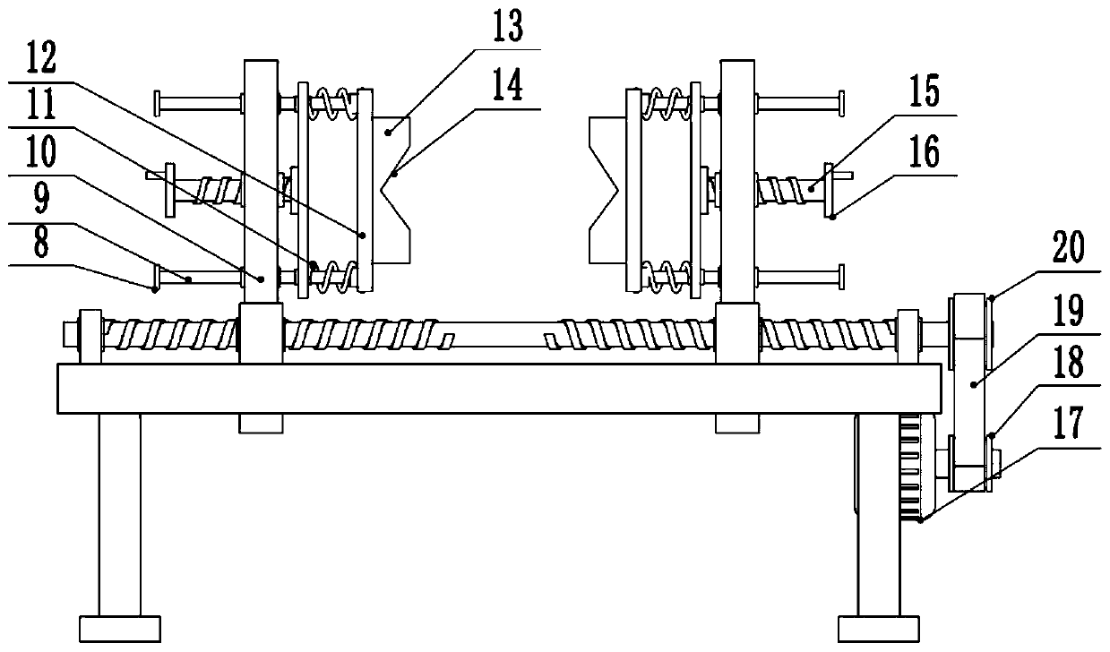
[0024] see Figure 1-3 , a clamping device with a pressure sensor, comprising a workbench 3, four corners of the lower surface of the workbench 3 are provided with support columns 2, the lower end of the support column 2 is provided with a pad 1, and the middle of the workbench 3 is provided with There is a chute 6, the chute 6 is slidably connected to the slider 7, the upper part of the slider 7 is provided with a fixed seat 10, the left and right ends of the workbench 3 are provided with a bearing seat 4, and the middle part of the bearing seat 4 is rotatably connected to the first wire Rod 5, the left and right sides of the first screw mandrel 5 are screwed to the middle part of the slide block 7, the left and right sides of the first screw mandrel 5 are provided with opposite threads, and the right side of the lower surface of the workbench 3 is provided with a drive motor 17 , the output shaft of the drive motor 17 is fixedly connected to the first pulley 18, the first pu...

Embodiment 2

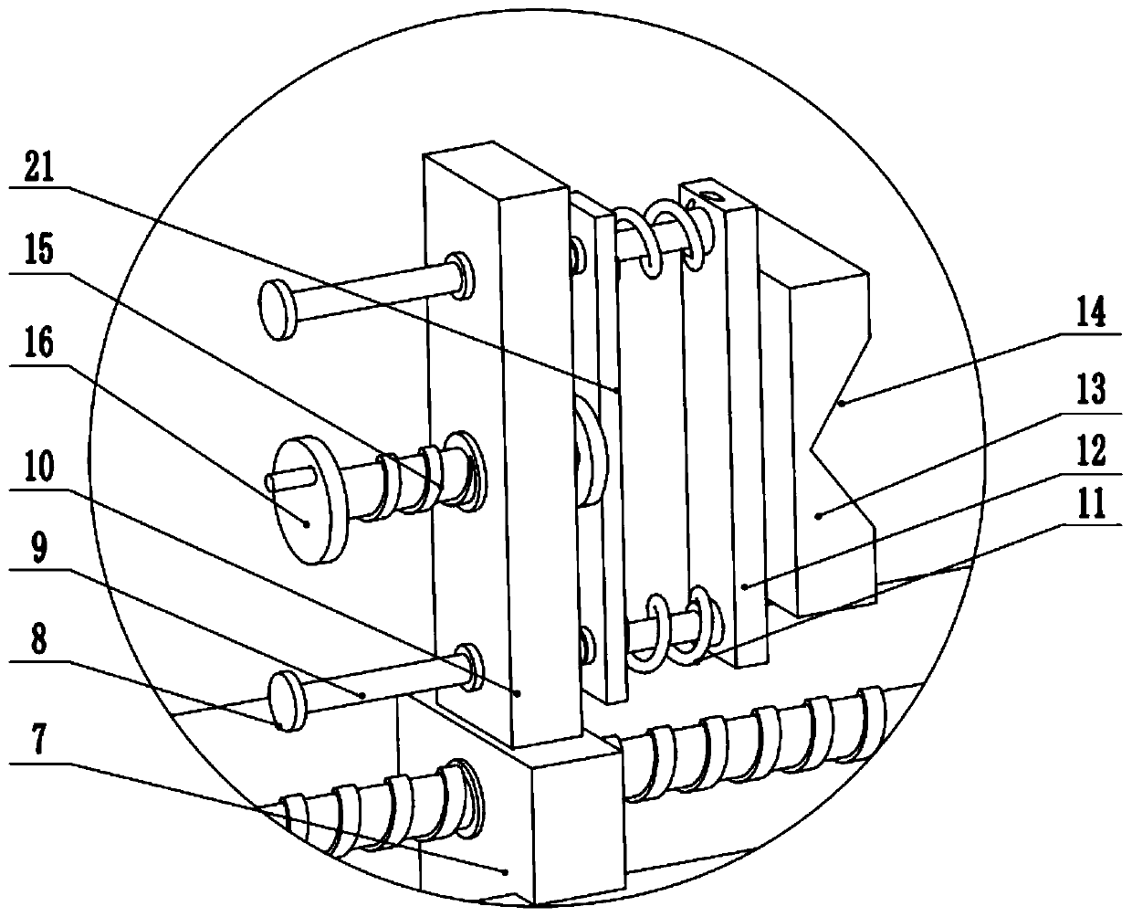
[0027] see figure 1 , the other content of this embodiment is the same as that of Embodiment 1, except that: the opposite side of the clamping block 13 is provided with a jaw 14 . In order to facilitate the clamping of various types of workpieces, jaws 14 of different sizes can be provided on the opposite surfaces of the clamping block 13, and the workpieces can be fixed through the jaws 14, and the workpieces will be more stable after being clamped. shaking.

[0028] In the implementation process of the present invention, the workpiece to be clamped is placed between the two clamping blocks 13. At this time, the drive motor 17 is started, and the drive motor 17 drives the first screw mandrel 5 to rotate through the belt 19 transmission. The left and right sides of the rod 5 are provided with threads with opposite rotations, so when the first screw rod 5 rotates, the two sliders 7 move close to each other, thereby driving the clamping blocks 13 to move close to each other, so...


PUM


Abstract

The invention relates to the technical field of clamping, and discloses a clamping device with a pressure sensor. The clamping device comprises a workbench, wherein a sliding groove is formed in the middle of the workbench, a sliding block is slidably connected to the sliding groove, a fixing seat is arranged on the upper portion of the sliding block, bearing seats are arranged at the left end andthe right end of the workbench, first screw rods are rotationally connected to the middle of the bearing seats, the left ends and the right ends of the first screw rods are in threaded connection with the middle of the sliding block, guide rods are connected to the upper end and the lower end of the fixing seats in a sliding mode, pressure sensors are connected to the sides, close to the center of the device, of the guide rods, and clamping blocks are connected to the sides, close to the center of the device, of the pressure sensors. According to the clamping device with the pressure sensor,a driving motor is arranged to drive the first screw rods to rotate, so that rapid clamping work of a workpiece can be achieved, meanwhile, second screw rods are arranged to adjust the distance between push plates and clamping blocks, so that the clamping force is accurately adjusted, the whole device is simple to operate, and the clamping device is suitable for popularization and application.

Description

technical field [0001] The invention relates to the field of clamping technology, in particular to a clamping device with a pressure sensor. Background technique [0002] In automation equipment, the clamping device is the most common equipment, which is used for loading and unloading products or parts in production; due to the clamping of products or parts, the splint needs to exert force on the parts or products; but this clamping force Difficult to control, if the clamping force is too large, the product will be deformed and affect the quality of the product; if the clamping force is too small, the product will fall during the clamping process due to lack of clamping force, resulting in product damage; existing In technology, in order to accurately control the clamping force of the splint on the product, a clamping force control component is often installed on the splint; however, adding a clamping force control component to the splint requires increasing the size of the ...

Claims


Application Information

Patent Timeline
IPC IPC(8): B25B11/00
CPCB25B11/00
Inventor 易宏博杨姗
Owner 湖南绚丽新材料科技有限公司
Why Eureka
Try Eureka