Mixture conveyor for concrete transportation

A technology for concrete and mixture, applied in the field of mixture conveyor, can solve the problems of affecting economic benefits, low degree of automation, high labor intensity, etc., and achieve the effects of convenient use, high practicability and reasonable structure

Active Publication Date: 2020-02-11
CCCC SHEC FOURTH ENG
View PDF10 Cites 2 Cited by
  • Summary
  • Abstract
  • Description
  • Claims
  • Application Information

AI Technical Summary

Problems solved by technology

After analysis, it is not difficult to find that this kind of transport vehicle has the defects of single function and low degree of automation, that is, the transport vehicle only realizes the transfer of prefabricated concrete, and transfers the transport vehicle from the mixing station to the molding station and transfers the transport vehicle to the molding station. The transfer of the concrete in the mold to the hopper at the molding station requires the participation of personnel, which makes the labor intensity of the personnel relatively high, which also leads to the production efficiency of the concrete prefabricated parts, and the mixing of the concrete requires an external equipment. Mixing soil mixer, which further affects the economic benefits of the factory of concrete prefabricated parts

Method used


Image

  • Mixture conveyor for concrete transportation
  • Mixture conveyor for concrete transportation
  • Mixture conveyor for concrete transportation

Examples


Embodiment Construction

[0020] In order to make the technical means, creative features, goals and effects achieved by the present invention easy to understand, the present invention will be further described below in conjunction with specific embodiments.

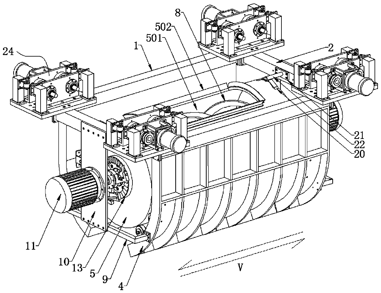
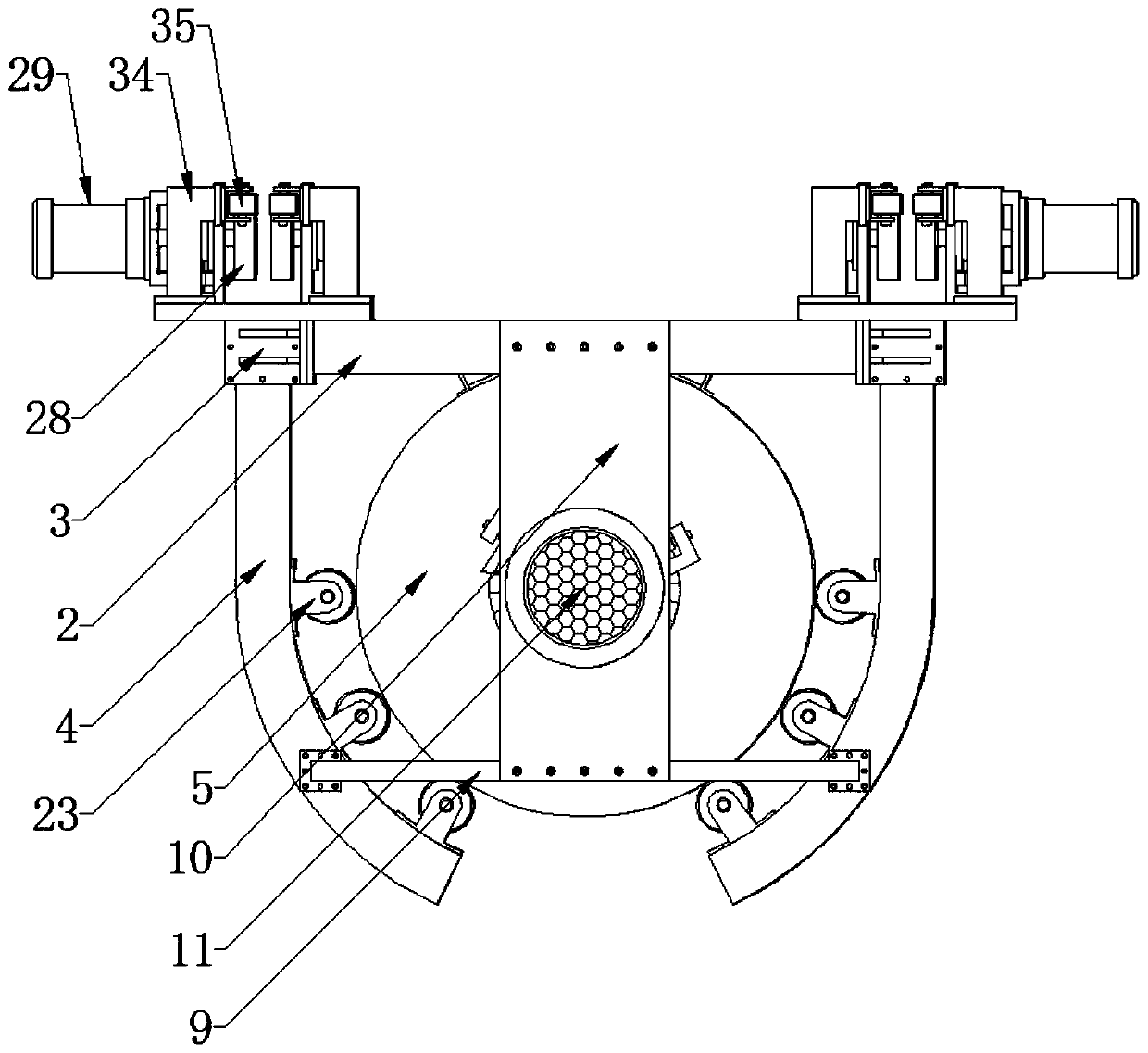
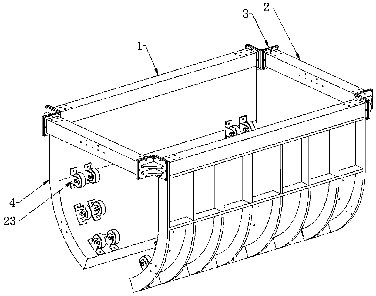
[0021] Such as Figure 1 to Figure 6 As shown, a mixture conveyor for concrete transportation includes installation pipe one 1, installation pipe two 2, baffle plate 4, mixing mechanism, turning mechanism and moving mechanism 24, and the installation pipe one 1 is provided with two Two installation pipes 1 and 2 are arranged parallel to each other and distributed toward the front and back. Two installation pipes 2 are arranged parallel to each other and distributed toward the left and right. The two installation pipes 1 and 2 install a rectangle and are connected by L-shaped The plate 3 is connected, the said baffle plate 4 is J-shaped and there are two, the two baffle plates 4 are distributed symmetrically on the left and right and installed on t...


PUM


Abstract

The invention discloses a mixture conveyor for concrete transportation, and relates to the technical field of transportation equipment. The mixture conveyor for concrete transportation includes firstinstallation tubes, second installation tubes, striker plates, a mixing mechanism, turnover mechanisms and a moving mechanism. The two first installation tubes are arranged and distributed in front and rear orientations. The two second installation tubes are arranged and distributed in left and right orientations. The two first installation tubes and the two second installation tubes form a rectangle and are connected through an L-shaped connecting plate. The two striker plates are arranged and the striker plates are in a J shape. The two striker plates are symmetrically distributed and installed on the lower end faces of the first installation tubes. The mixing mechanism is arranged between the two striker plates and is used for mixing and stirring sand, stone, water and cement, and avoiding arranging a mixer outside independently. The turnover mechanisms are arranged at the front and rear sides of the mixing mechanism and are used for the overturn of the mixing mechanism to pour outthe mixed concrete. The moving mechanism is arranged over the connecting plate and used for moving the mixing mechanism so as to move the mixing mechanism to the position over the specified position.

Description

technical field [0001] The invention relates to the technical field of transportation equipment, in particular to a mixture conveyor for concrete transportation. Background technique [0002] In the process of making concrete prefabricated parts, it is necessary to transport a large amount of concrete material from the mixing station to the molding station. The current solution is to use a transport vehicle, that is, when the transport vehicle stops under the mixing station, it uses the bucket to receive the blanking material , After being filled, it will be driven to the molding station, and the concrete material will be transferred to the corresponding hopper. After analysis, it is not difficult to find that this kind of transport vehicle has the defects of single function and low degree of automation, that is, the transport vehicle only realizes the transfer of prefabricated concrete, and transfers the transport vehicle from the mixing station to the molding station and t...

Claims


Application Information

Patent Timeline
Patent Type & Authority Applications(China)
IPC IPC(8): B28C5/14B28C7/16B28B13/02
CPCB28C5/14B28C5/141B28C5/0806B28C5/0831B28C5/0893B28C7/16B28B13/026B28B13/02
Inventor 王耐夏辉尤琦章晓明张志鹏喻洋洋王晓斌
Owner CCCC SHEC FOURTH ENG
Why Eureka
Try Eureka