Clamping die device

A technology of mold clamping and mold base, which is applied in the field of mold clamping devices, can solve the problems of small force range, narrow application range, and high cost, and achieve the effect of large force range, wide application range and good effect of the cylinder

Pending Publication Date: 2020-02-11
OMS MASCH CO LTD
View PDF0 Cites 0 Cited by
  • Summary
  • Abstract
  • Description
  • Claims
  • Application Information

AI Technical Summary

Problems solved by technology

[0003] However, in the mold clamping device of the above-mentioned prior art, the force effect of the cylinder 100 in this design is poor, and the force range is small. For clamping molds that require a larger thrust, a cylinder with a greater thrust is needed, or even a cylinder with a greater thrust is required. Increase the cylinder to achieve
Therefore, this design cylinder in the prior art has a small force range, narrow application range, poor effect and high cost

Method used


Image

  • Clamping die device
  • Clamping die device
  • Clamping die device

Examples


Embodiment Construction

[0015] Below, in conjunction with accompanying drawing and specific embodiment, the present invention is described further:

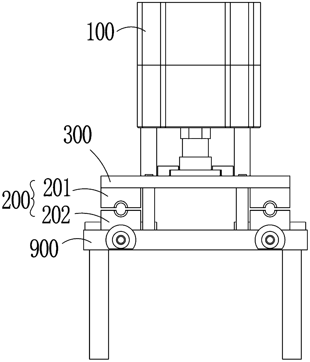
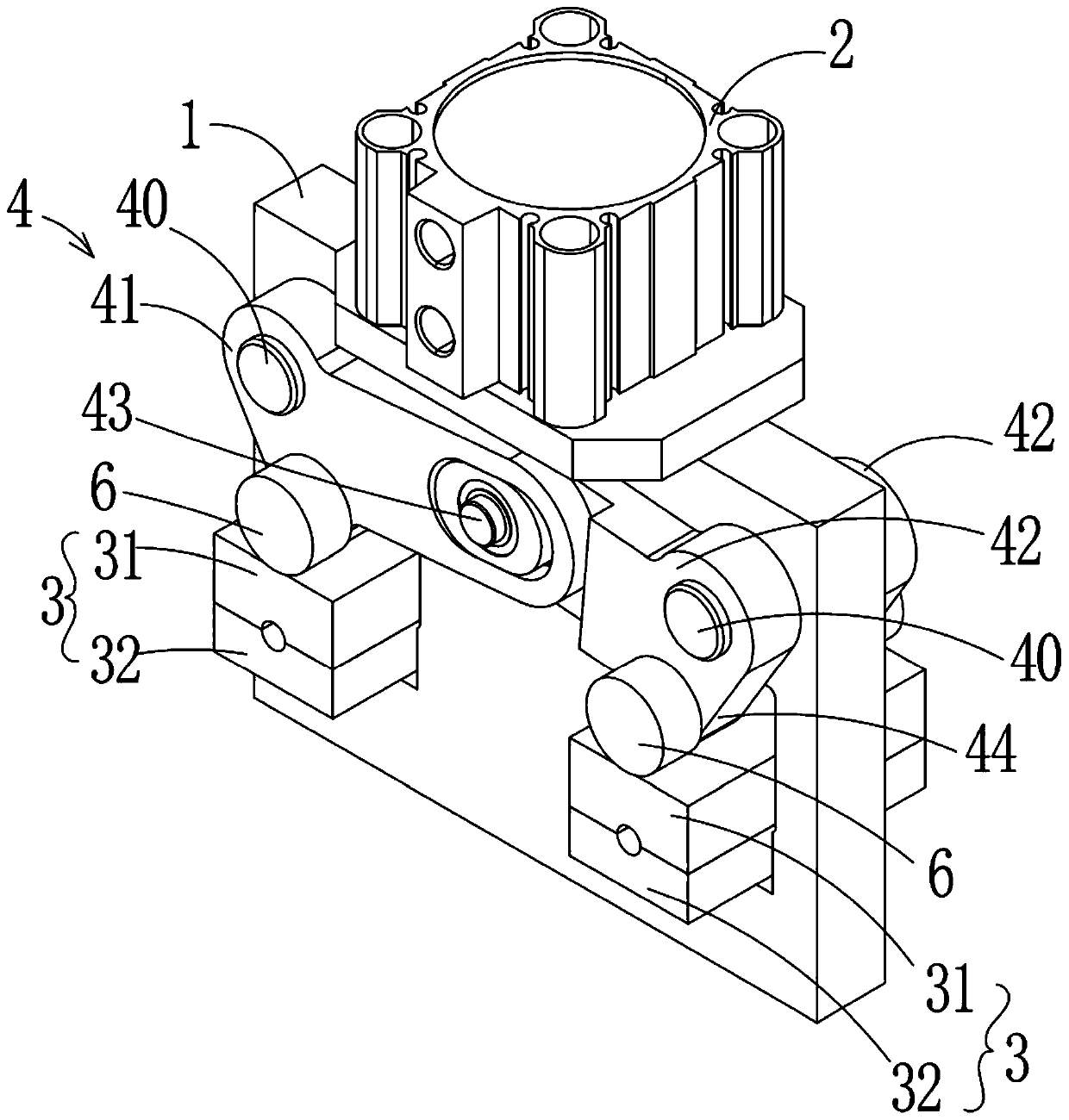
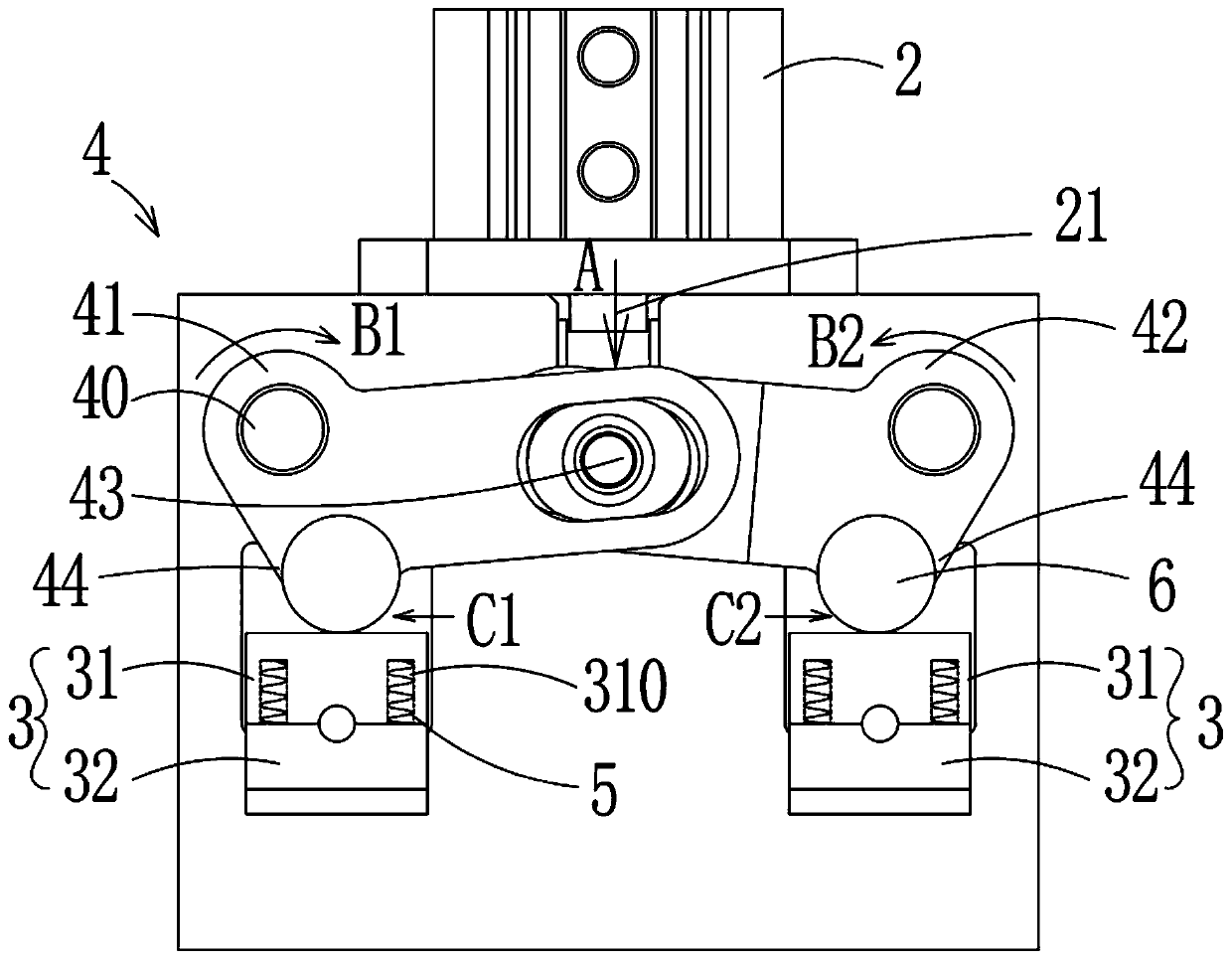
[0016] Figure 2 to Figure 5 Disclosed is an embodiment of the mold clamping device, a clamping mold device comprising a mounting plate 1, a cylinder 2 and a set of clamping molds 3 with an upper mold base 31 and a lower mold base 32 respectively, the clamping molds 3 are installed On the mounting plate 1, a link assembly 4 is also included, and the link assembly 4 includes a first swing arm 41, a second swing arm 42 and a first connecting shaft 43. In this embodiment, specifically, the first There are two groups of swing arms 41 and second swing arms 42 respectively, the first ends of the first swing arms 41 and the second swing arms 42 are pivotally connected to the first connecting shaft 43 and can rotate around the first connecting shaft 43, The second ends of the first swing arm 41 and the second swing arm 42 are respectively mounted on the mounti...


PUM


Abstract

The invention discloses a clamping die device. The clamping die device comprises a mounting plate, an air cylinder and a set of clamping dies, wherein each clamping die is provided with an upper die base and a lower die base, and the clamping dies are mounted on the mounting plate. The clamping die device further comprises a connecting rod assembly, and the connecting rod assembly comprises firstswing arms, second swing arms and a first connecting shaft; the first ends of the first swing arms and the first ends of the second swing arms are pivotally connected with the first connecting shaft and can rotate around the first connecting shaft, the second ends of the first swing arms and the second ends of the second swing arms are installed on the mounting plate separately and can rotate, thefirst swing arms and the second swing arms are provided with pressing blocks respectively, and the pressing blocks abut against the upper surfaces of the upper die bases; and a piston rod of the aircylinder is connected with the first connecting shaft and can drive the first connecting shaft to reciprocate up and down, the first swing arms and the second swing arms are driven to swing accordingly, and in the swing stroke of the first swing arms and the second swing arms, the pressing blocks complete the action of releasing or pressing the upper die bases. The clamping die device has the advantages that the acting force range of the air cylinder is large, the application range is wide, the acting effect is good, and the cost is low.

Description

technical field [0001] The invention relates to the field of clamping devices, in particular to a clamping device. Background technique [0002] At present, the structure of the clamping device of the cutting machine is as follows: figure 1 As shown, it specifically includes a support table 900, a cylinder 100, a clamping mold 200, and a connecting plate 300. The first surface of the connecting plate 300 is installed on the piston rod end of the cylinder 100 and is driven to reciprocate by the piston rod. The clamping mold 200 includes an upper The clamping die 201 and the lower clamping die 202 matched with the upper clamping die 201, the upper clamping die 201 is installed on the second surface of the connection plate 300, and the piston rod of the cylinder 100 drives the connection plate 300 to reciprocate up and down, thereby driving the upper clamp The mold 201 reciprocates up and down to open or close the clamping mold 200, so as to realize the loosening and clamping ...

Claims


Application Information

Patent Timeline
Patent Type & Authority Applications(China)
IPC IPC(8): B29C33/24
CPCB29C33/24
Inventor 龙晓斌曹敏
Owner OMS MASCH CO LTD
Why Eureka
Try Eureka