Component for a motor vehicle

A technology for components and automobiles, applied in the direction of vehicle components, superstructure, superstructure sub-assemblies, etc., can solve problems such as damage to plastics, temperature rise, etc., to achieve high mechanical load, withstand mechanical load, and strengthen the effect of strength

Inactive Publication Date: 2007-01-17
BEHR GMBH & CO KG
View PDF1 Cites 0 Cited by
  • Summary
  • Abstract
  • Description
  • Claims
  • Application Information

AI Technical Summary

Problems solved by technology

Heat input on the outside of the beam causes the temperature on the inside to rise rapidly, which can damage the plastic that forms the ventilation ducts

Method used


Image

  • Component for a motor vehicle
  • Component for a motor vehicle
  • Component for a motor vehicle

Examples


Embodiment Construction

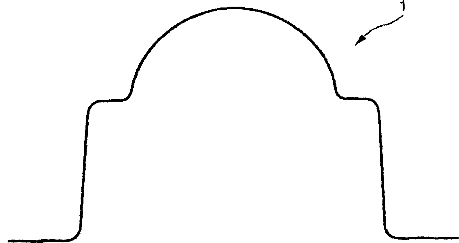
[0033] FIG. 1 shows, in cross-section, a metal beam 1 with a known operating principle, which forms the body of a component according to the invention, which will be described in more detail below. The crossbeam 1 , also referred to as the dashboard support, is arranged as a support part of the body structure between the A-pillars of the vehicle and forms a mechanical connection with other components, such as the airbag housing.

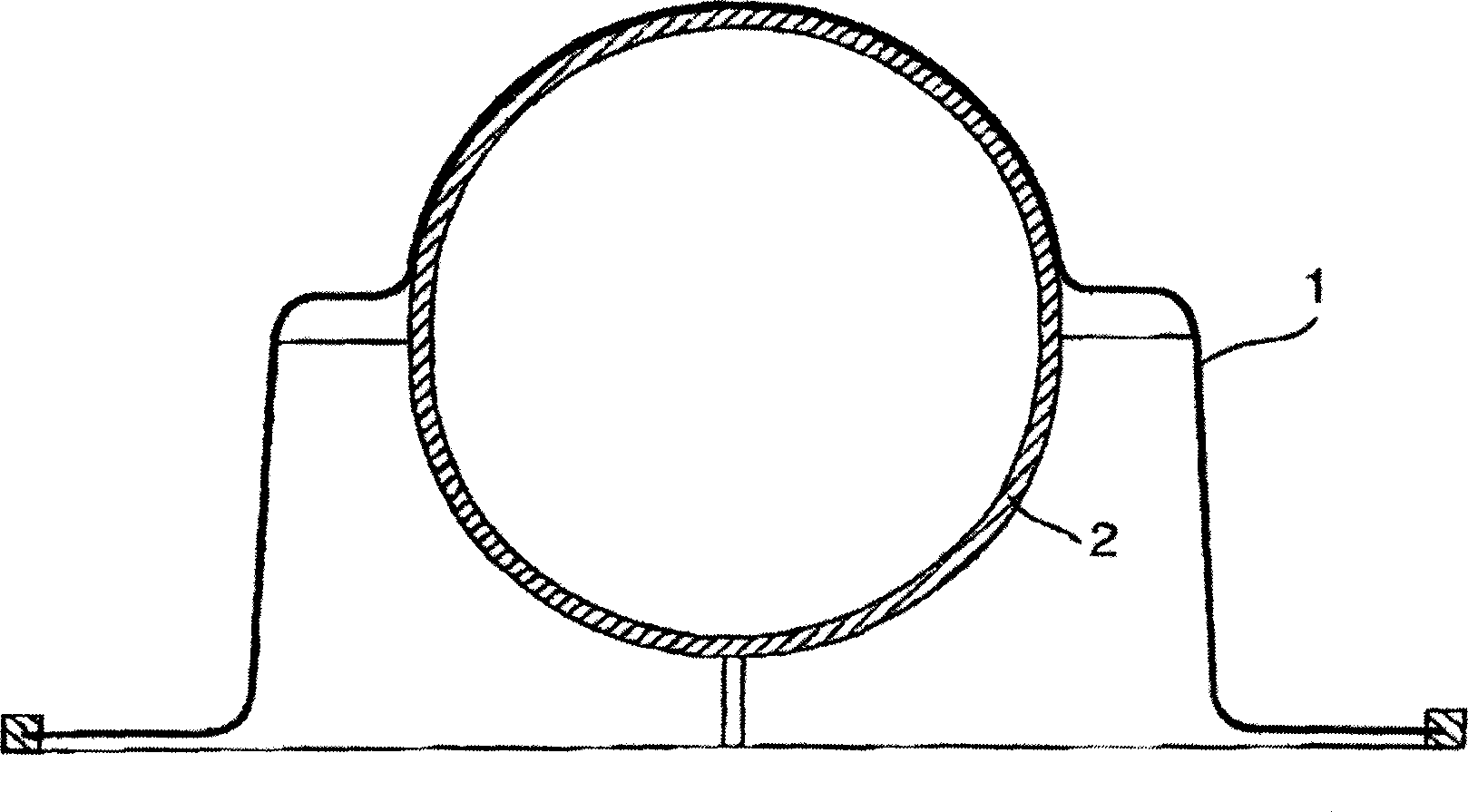
[0034] The same principle of operation is known, for example, in DE 100 64 522 A1, in the arrangement according to FIG. 2 , with a cross member 1 having a circular cross-section duct or ventilation duct 2 which is produced from plastic by injection molding. Ventilation ducts 2 , which at least slightly increase the stability of the cross member 1 , extend along the cross member 1 , so that the supply air is distributed in the transverse direction of the vehicle.

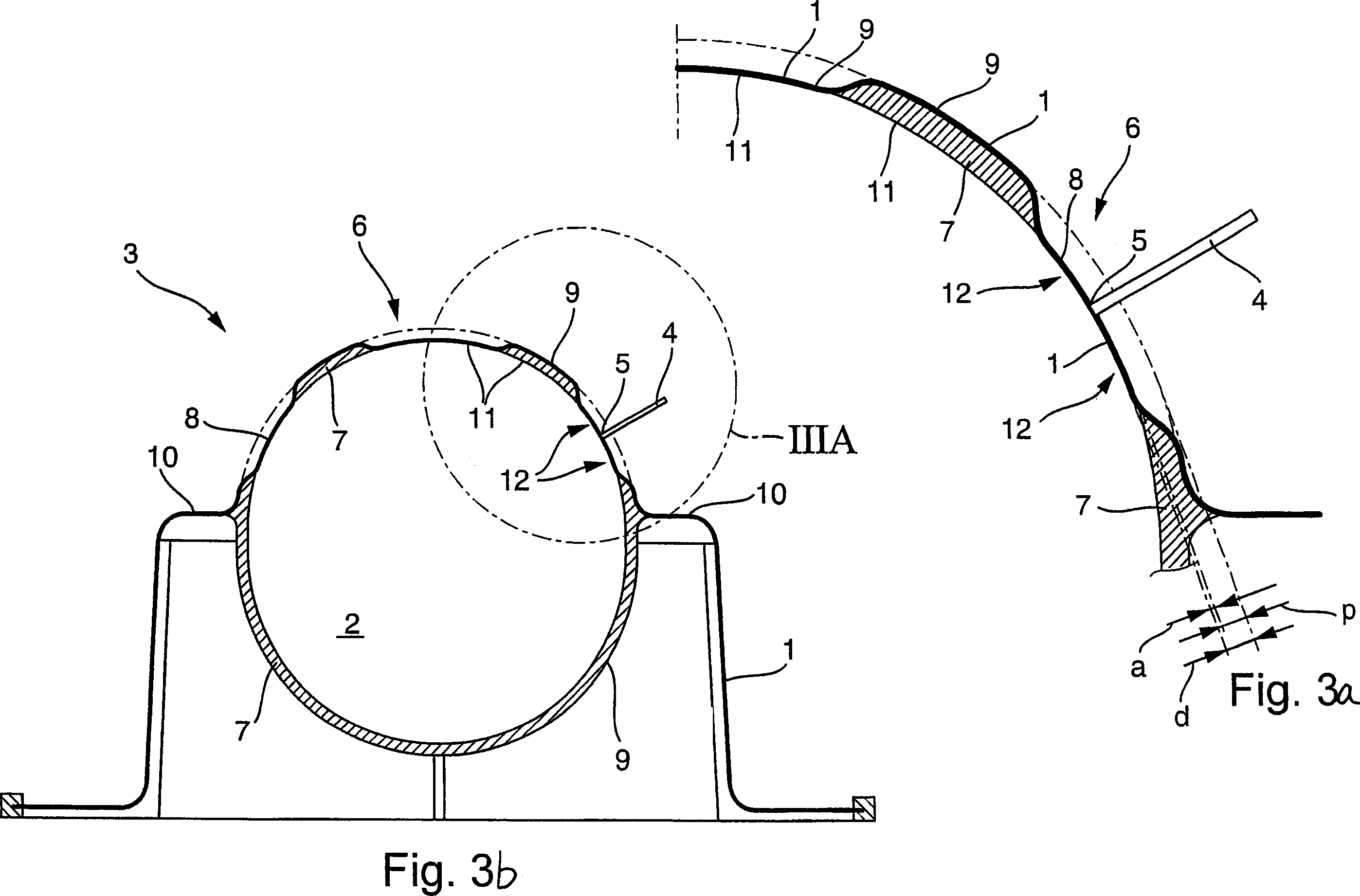
[0035] In FIGS. 3 a and 3 b , the structural principle of the component 3 according to ...


PUM


Abstract

Crossbeam comprises a joining part (4) forming a material bond with a base body (1) or a part rigidly connected to it at a joining point (5) to create an intermediate area (12) to reduce heat transfer between the joining part and the plastic (7) of a channel (2) and / or drain away a gas produced during the joining process. - Preferred Features: The channel is joined to the base body by plastic injection molding. The joining point is arranged directly on the base body. The base body has an embossed structure (6) in the region for fixing the joining part.

Description

technical field [0001] The present invention relates to a component, in particular a crossbeam arranged between the A-pillars of a motor vehicle, comprising a metal body substantially in the shape of a tube or consisting of an elongated shell open in outline, and at least one A plastic pipe, such as a ventilation pipe, partly surrounded by the contour of the body and mechanically connected to the body. Such a component is disclosed, for example, in DE 100 64 522 A1. Background technique [0002] In a car, the cross member that connects the A-pillars doubles as an air duct, which saves weight and / or space. Covering the beam with plastic both increases its stability and reduces the chance of condensation of moisture contained in the air that is conditioned to be sent to the interior of the car. The connection points for other components such as the steering column or the airbags are arranged on the cross member. Such connection points are usually realized by connectors weld...

Claims


Application Information

Patent Timeline
IPC IPC(8): B62D25/14B62D29/00B62D29/04
CPCB62D29/005B62D29/001B62D29/004B62D25/142
Inventor 托马斯·法伊特约亨·施米茨福尔克尔·温霍茨瓦尔特·沃尔夫
Owner BEHR GMBH & CO KG
Why Eureka
Try Eureka