Tire disassembling and assembling machine
A tire changer and wheel technology, applied in tire installation, tire parts, transportation and packaging, etc., can solve the problems of low disassembly and assembly efficiency, large floor space, etc. needs, and the effect of improving work efficiency
- Summary
- Abstract
- Description
- Claims
- Application Information
AI Technical Summary
Problems solved by technology
Method used
Image

Examples
Embodiment 1
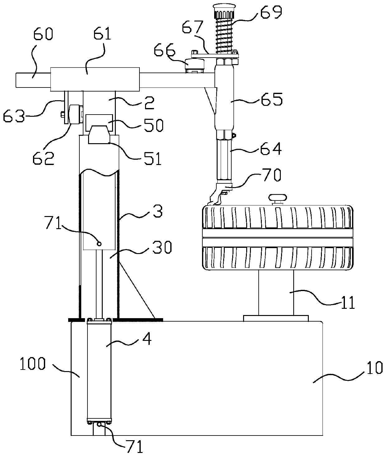
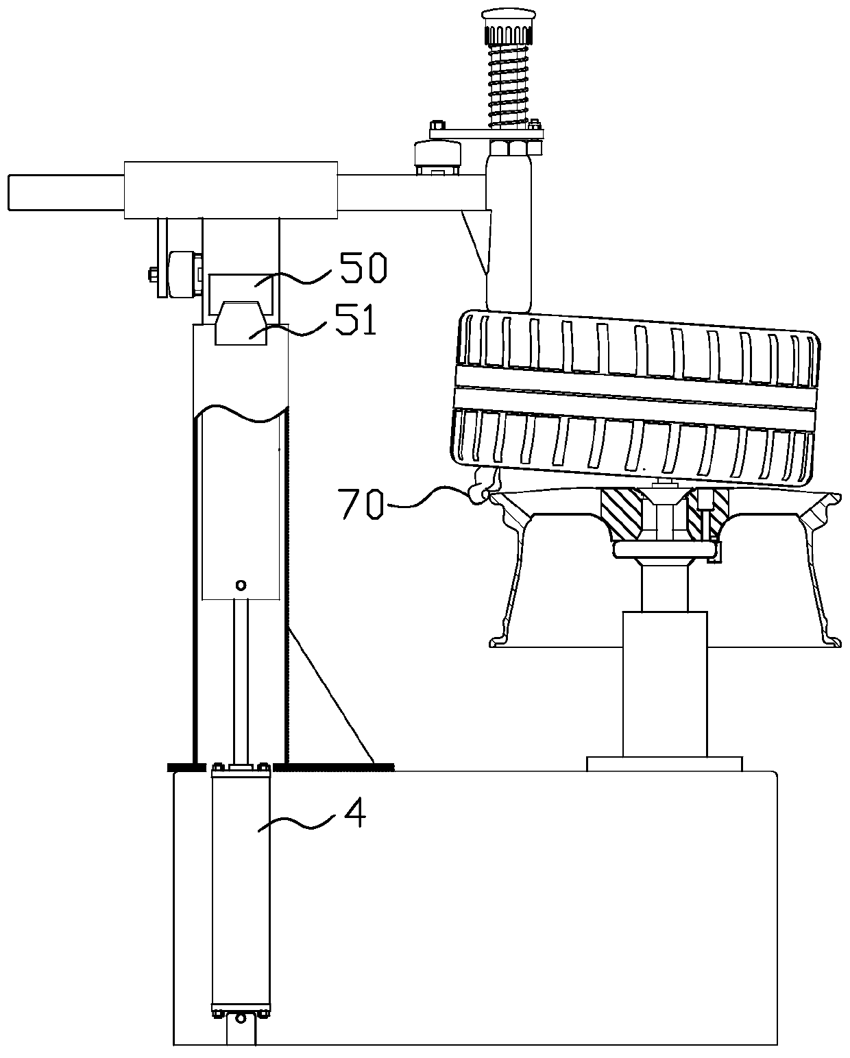
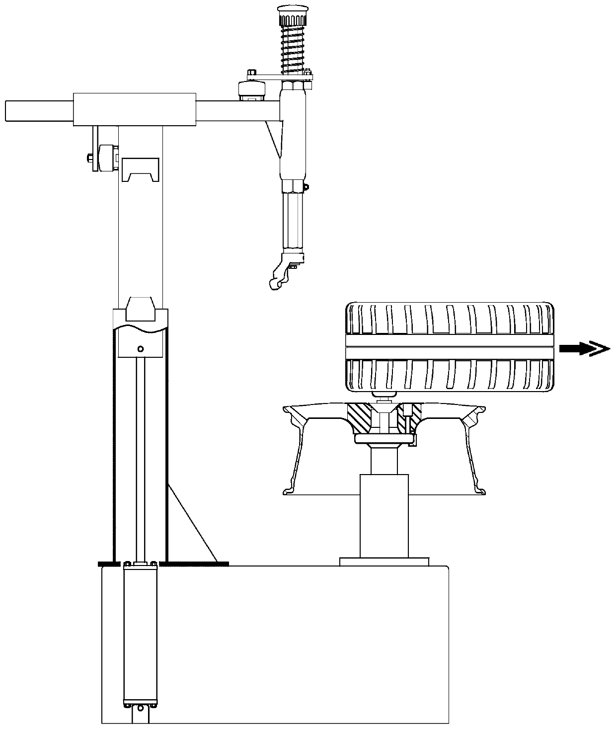
[0038] Such as figure 1 Shown is the tire changer disclosed in the present invention, including a base 10, a wheel holder 11 mounted on the base 10, and a drive dismounting tool 70 arranged on the base 10 in the horizontal direction and The tool carrying device moving in the vertical direction also includes a sliding body 2, a support body 3 and a first driving device 4; the first driving device 4 can be a linear driving device such as a pneumatic cylinder, a hydraulic cylinder, etc., and the first driving device 4 is installed In the base 10, in this embodiment, the first driving device is a hydraulic cylinder, and the base 10 has an accommodation space 100, and the lower end of the hydraulic cylinder is hinged on the bottom surface of the accommodation space 100 through a rotating shaft 71. The support body 3 is fixed on the seat 10, and the support body 3 is provided with a first sliding cavity 30. In this implementation, the support body 3 adopts a polygonal pipe structure...
Embodiment 2
[0053] Such as Figure 6 Shown is the second embodiment of the tire changer disclosed in the present invention. The difference between this embodiment and Embodiment 1 is that, in Embodiment 1, the support body is provided with a first sliding cavity (that is, the support body can be The inner diameter is a polygonal tube structure), the lower part of the sliding body is placed in the sliding cavity of the supporting body (the supporting body is sleeved on the sliding body), and the first driving device can drive the sliding body to slide vertically in the first sliding cavity of the supporting body.
[0054] In this embodiment, the sliding body 2 is provided with a second sliding chamber 20. Preferably, the sliding body is a tube structure with a polygonal inner diameter. The sliding body 2 is set on the supporting body 3, and one end of the first driving device is installed on the base. The other end is connected to the outer wall of the sliding body, and the first driving d...
Embodiment 3
[0056] Such as Figure 7 Shown is the third embodiment of the tire changer disclosed in the present invention. The difference between this embodiment and Embodiment 1 is that, in Embodiment 1, the support body is provided with a first sliding chamber (that is, the support body can be The inner diameter is a polygonal tube structure), the lower part of the sliding body is placed in the sliding cavity of the supporting body (the supporting body is sleeved on the sliding body), and the first driving device can drive the sliding body to slide vertically in the first sliding cavity of the supporting body.
[0057] In this embodiment, the sliding body 2 is provided with a second sliding cavity 20, preferably, the sliding body is a tube structure with a polygonal inner diameter (the inner diameter of the tube forms the second sliding cavity), and the supporting body 3 is provided with an accommodating cavity 31 , preferably, the support body is a polygonal tube structure with an inne...
PUM
 Abstract
Description
Claims
Application Information
 - R&D
- Intellectual Property
- Life Sciences
- Materials
- Tech Scout
- Unparalleled Data Quality
- Higher Quality Content
- 60% Fewer Hallucinations
Browse by: Latest US Patents, China's latest patents, Technical Efficacy Thesaurus, Application Domain, Technology Topic, Popular Technical Reports.
© 2025 PatSnap. All rights reserved.Legal|Privacy policy|Modern Slavery Act Transparency Statement|Sitemap|About US| Contact US: help@patsnap.com