Electromagnetic driving device and gas proportional valve with same

An electromagnetic drive and magnet guide technology, which is applied in the direction of electromagnets, valve devices, electrical components, etc., can solve the problems that affect the reliability of electromagnetic drive devices and the inability of moving coil parts to obtain sufficient magnetic thrust.

Active Publication Date: 2020-02-11
ZHEJIANG SANHUA INTELLIGENT CONTROLS CO LTD
View PDF6 Cites 3 Cited by
  • Summary
  • Abstract
  • Description
  • Claims
  • Application Information

AI Technical Summary

Problems solved by technology

[0002] The electromagnetic drive device includes a permanent magnet, a magnetic core and a coil part. The magnetic field generated by the electrification of the coil part interacts with the magnetic field generated by the permanent magnet, so that the coil part drives the valve plug close to or away from the valve port. When the magnetic force obtained by the coil part The larger it is, the more beneficial it is to accurately scale the actuation accuracy of the valve plug, and the magnetic force of the electromagnetic drive device is weak, so the movable coil part cannot obtain enough magnetic thrust for normal actuation, thus affecting the actuation of the electromagnetic drive device reliability

Method used


Image

  • Electromagnetic driving device and gas proportional valve with same
  • Electromagnetic driving device and gas proportional valve with same
  • Electromagnetic driving device and gas proportional valve with same

Examples


Embodiment Construction

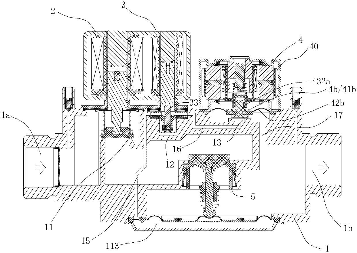
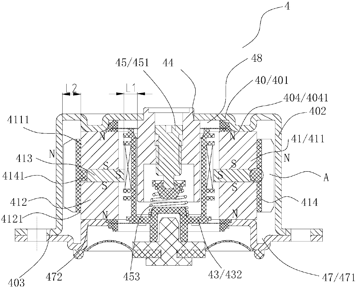
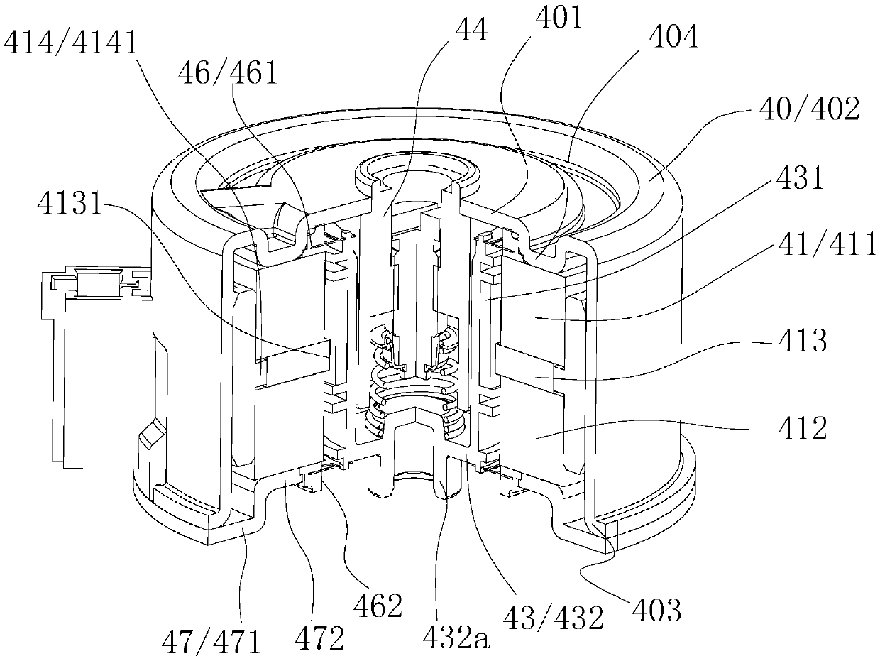
[0010] Such as figure 1 In the shown electromagnetic driving device, the electromagnetic driving device is provided with a cavity 48. The electromagnetic driving device includes a casing 40 and a magnetically conductive core 44. The casing 40 includes at least a magnetically conductive part, and the magnetically conductive part includes a top wall part 401 and a side wall part 402. , the top wall portion 401 is fixedly connected with the magnetically conductive core 44, the outer peripheral portion of the magnetically conductive core 44 is provided with a moving coil assembly 43, and the moving coil assembly 43 can reciprocate along the axial direction of the magnetically conductive core 44, and the electromagnetic drive part also includes a magnet Component 41, the magnet component 41 includes a first permanent magnet 411, a second permanent magnet 412, and a soft magnet 413 located between the first permanent magnet 411 and the second permanent magnet 412. It should be noted ...


PUM


Abstract

The invention discloses an electromagnetic driving device. The electromagnetic driving device comprises a shell, a magnetic conduction core and a magnet assembly, wherein the shell at least comprisesa magnetic conductive portion, the magnetic conductive portion comprises a top wall portion and a side wall portion, and the top wall portion is fixedly connected with the magnetic conduction core; and the magnet assembly comprises a first permanent magnet, a second permanent magnet and a soft magnet, wherein the soft magnet is located between the first permanent magnet and the second permanent magnet, the magnet assembly is located in an electromagnetic drive device cavity, the soft magnet and the magnetic conduction core form a first interval, the first permanent magnet and the sidewall portion of the second permanent magnet form a second interval, and the first interval is less than the second interval. When the magnetic force is transmitted, the magnetic conductive portion can providea transmission effect for the magnetic force, the first permanent magnet and the second permanent magnet can be fully magnetized on the soft magnet, and meanwhile the first interval is less than the second interval, so that the magnetic force is more focused on the first interval formed by the soft magnet and the magnetic conduction core; and the electromagnetic driving device can obtain sufficient magnetic thrust to reciprocate along the axis direction of the magnetic conduction core when being powered on, so that the magnetic performance is improved, and the actuation reliability of the electromagnetic driving device can be relatively improved.

Description

technical field [0001] The invention relates to the technical fields of electromagnetic drive control and gas control, in particular to an electromagnetic drive device and a gas proportional valve using the electromagnetic drive device. Background technique [0002] The electromagnetic drive device includes a permanent magnet, a magnetic core and a coil part. The magnetic field generated by the electrification of the coil part interacts with the magnetic field generated by the permanent magnet, so that the coil part drives the valve plug close to or away from the valve port. When the magnetic force obtained by the coil part The larger it is, the more beneficial it is to accurately scale the actuation accuracy of the valve plug, and the magnetic force of the electromagnetic drive device is weak, so the movable coil part cannot obtain enough magnetic thrust for normal actuation, thus affecting the actuation of the electromagnetic drive device reliability. Contents of the inv...

Claims


Application Information

Patent Timeline
Patent Type & Authority Applications(China)
IPC IPC(8): F16K31/06H01F7/126H01F7/16
CPCF16K31/0675H01F7/081H01F7/126H01F7/1607
Inventor 不公告发明人
Owner ZHEJIANG SANHUA INTELLIGENT CONTROLS CO LTD
Why Eureka
Try Eureka