
Electronic expansion valve

A technology of electronic expansion valve and valve body, which is applied in the direction of lifting valve, valve details, valve device, etc., and can solve the problems of output shaft eccentricity and electronic expansion valve unreliable actuation.

Active Publication Date: 2020-03-31
ZHEJIANG SANHUA INTELLIGENT CONTROLS CO LTD
View PDF17 Cites 0 Cited by
  • Summary
  • Abstract
  • Description
  • Claims
  • Application Information

AI Technical Summary

Problems solved by technology

[0002] The electronic expansion valve structure of the gear-type reduction device generally includes a gear-type reduction device, a transmission part and a valve needle assembly. The gear-type reduction device includes a fixed gear and a transmission gear. The transmission gear is provided with a gear shaft. The transmission part includes a nut. When the pulse signal is applied, the transmission gear and the gear shaft rotate together, and the gear shaft and the nut drive the valve needle assembly close to or away from the valve port through thread cooperation to adjust the refrigerant flow through the valve port, and the weight of the entire gear reduction device is equivalent to Loaded by the output shaft, the output shaft is likely to cause eccentricity when the product is frequently operated, which will cause the electronic expansion valve to operate unreliably

Method used


Image

  • Electronic expansion valve
  • Electronic expansion valve
  • Electronic expansion valve

Examples


Embodiment 1

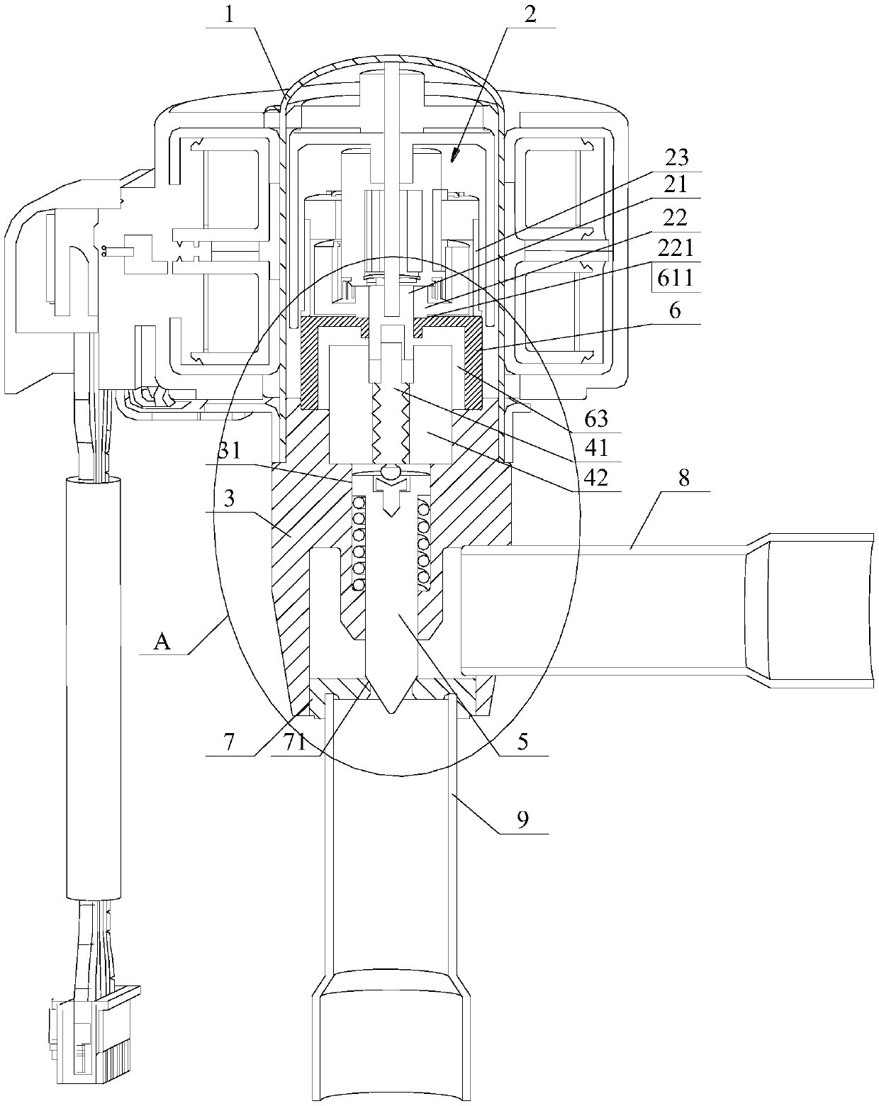
[0014] Please refer to figure 1 , which is a schematic diagram of the overall structure of the electronic expansion valve described in this embodiment.

[0015] The electronic expansion valve includes a housing 1 and a planetary gear reduction device 2 arranged in the housing 1. Its specific transmission principle is the same as that of the prior art. The output gear 22 and the output shaft 21 output power to the screw rod 41 of the nut drive assembly to drive the valve core assembly 5 to carry out axial lifting movement, so as to approach or stay away from the valve port 71 on the valve core seat 7 to realize the adjustment of the valve opening. adjust.

[0016] The housing 1 of the electronic expansion valve is fixedly connected to the valve body 3, the valve body 3 is fixedly connected to the valve seat core 7, the valve body 3 is provided with a cavity 31, at least part of the nut drive assembly (41, 42) and at least part of the valve needle The component 5 is located in...

Embodiment 2

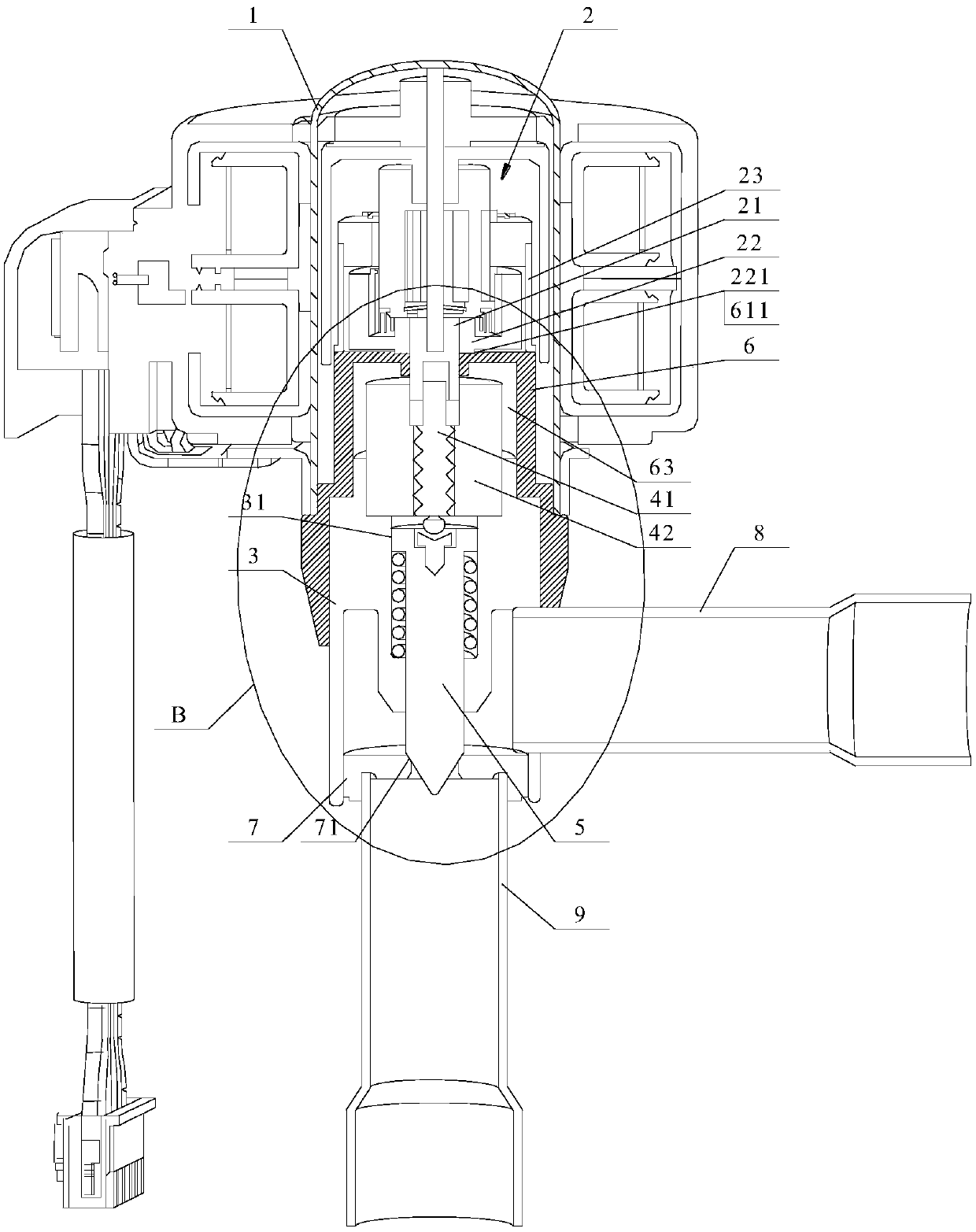
[0025] See image 3 , which is a schematic diagram of the overall structure of the electronic expansion valve described in Embodiment 2.

[0026] The difference between this solution and the first embodiment is that the fixing methods of the support member 6 and the valve body 3 are different. In order to clearly show the differences and connections between the two, the same functional components are shown with the same symbols in the drawings.

[0027] As shown in the figure, the extension portion 62 of the support member 6 has a small diameter portion 621, a large diameter portion 623 and a first step portion 622, the small diameter portion 621 is connected to the main body portion 61, and the small diameter portion 621 and the large diameter portion 623 pass through the first step portion 622 connection; the lower end of the housing 1 is fixedly connected to the valve body 3 through the extension 62 . Specifically, it can be fixed by welding or pressing. further combined...


PUM


Abstract

The invention discloses an electronic expansion valve. A valve body of the electronic expansion valve is fixedly connected with a valve seat core, the valve seat core is provided with a valve port, asupporting assembly of the valve seat core is fixedly connected with the valve body, and a shell is fixedly connected with the valve body or the supporting assembly. The supporting assembly comprisesa supporting table and a guide part, a gear speed reduction device comprises an output gear and an output shaft, and at least a part of the output gear abuts against the supporting table and is supported by the supporting table; and a guide hole is formed in the guide part, the guide hole is matched with the output shaft, and the guide part supplies a guiding effect to the output shaft. A nut transmission assembly comprises a nut and a screw rod, the output shaft penetrates through the guide hole to be in transmission connection with the screw rod, a valve needle assembly is in threaded fit action with the nut through the screw rod, and the valve needle assembly can achieve axial lifting motion so as to be close to or far away from the valve port. By means of the electronic expansion valve, the output gear can be effectively supported and guided, the phenomenon that the force is applied to a gear shaft to generate actuation eccentricity and the like can be avoided, and it is guaranteedthat the actuation reliability of the electronic expansion valve can be effectively improved.

Description

technical field [0001] The invention relates to the technical field of refrigeration control, in particular to an electronic expansion valve. Background technique [0002] The electronic expansion valve structure of the gear-type reduction device generally includes a gear-type reduction device, a transmission part and a valve needle assembly. The gear-type reduction device includes a fixed gear and a transmission gear. The transmission gear is provided with a gear shaft. The transmission part includes a nut. When the pulse signal is applied, the transmission gear and the gear shaft rotate together, and the gear shaft and the nut drive the valve needle assembly close to or away from the valve port through thread cooperation to adjust the refrigerant flow through the valve port, and the weight of the entire gear reduction device is equivalent to It is carried by the output shaft, and the output shaft is likely to cause eccentricity when the product is frequently operated, whic...

Claims


Application Information

Patent Timeline
Patent Type & Authority Applications(China)
IPC IPC(8): F16K1/42F16K27/02F16K31/50F16K31/53F25B41/06F25B41/34
CPCF16K31/53F16K31/50F16K1/42F16K27/0254F25B41/34F25B41/31Y02B30/70
Inventor 不公告发明人
Owner ZHEJIANG SANHUA INTELLIGENT CONTROLS CO LTD
Learn More