Supercharge Your Innovation With Domain-Expert AI Agents!

Petroleum production pipeline rack

A pipe rack and petroleum technology, applied in the direction of pipe racks, pipes/pipe joints/fittings, mechanical equipment, etc., which can solve the problems of unable to fix and clamp pipes

Active Publication Date: 2020-02-11
东港智科产业园有限公司
View PDF8 Cites 0 Cited by
  • Summary
  • Abstract
  • Description
  • Claims
  • Application Information

AI Technical Summary

Problems solved by technology

[0002] For example, Patent No. CN201721580181.5 is a pipe erection device; the pipe erection device includes: a first clamp and a second clamp, and the first clamp and the second clamp are respectively suitable for clamping On both sides of the column; clip fixing parts, the clip fixing parts are respectively connected with the first clip and the second clip and are used to change the first clip and the second clip The relative distance between the second clamping parts, thereby changing the clamping force of the first clamping part and the second clamping part to clamp the column; the pipe fixing part, the pipe fixing part is arranged on Between the first clamping part and the second clamping part; the disadvantage of this utility model is that it cannot fix and clamp pipes of different heights and diameters

Method used


Image

  • Petroleum production pipeline rack
  • Petroleum production pipeline rack
  • Petroleum production pipeline rack

Examples


specific Embodiment approach 1

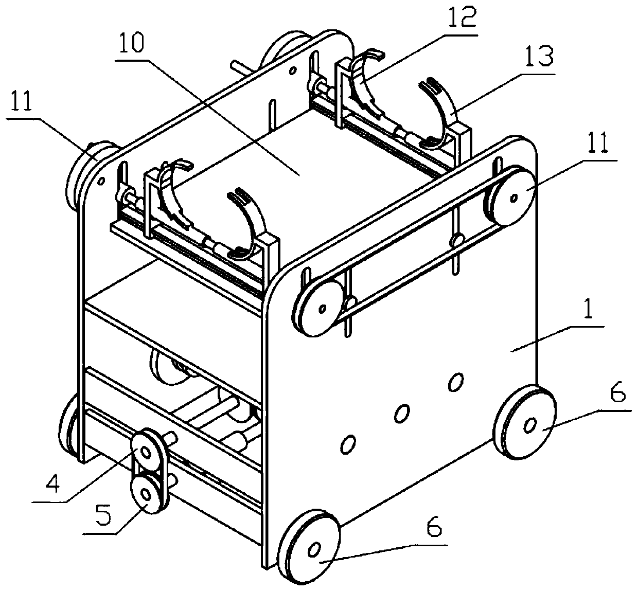
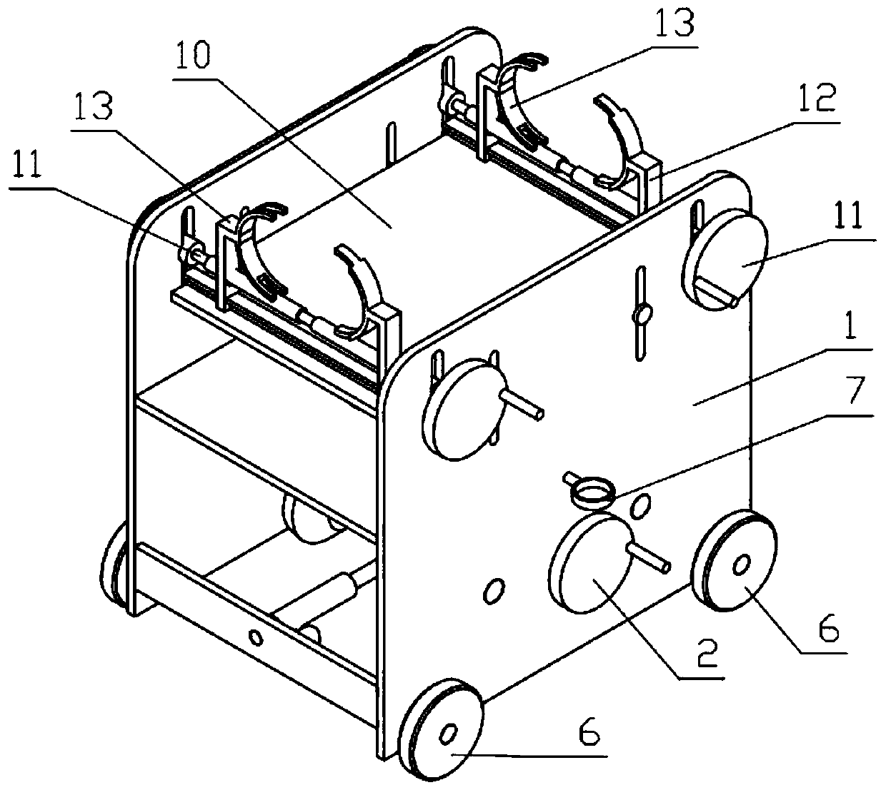
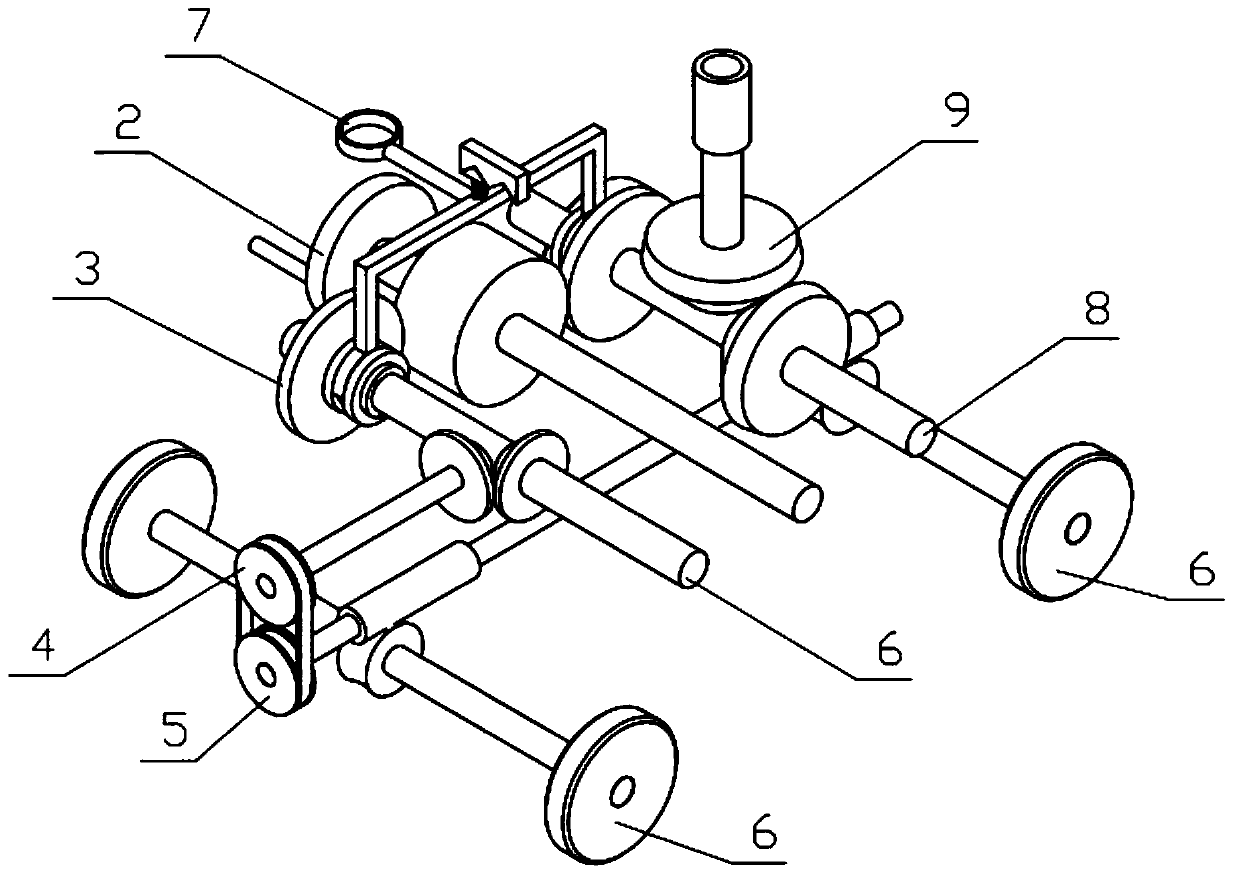
[0044] Combine below Figure 1-20 Description of this embodiment, a petroleum oil production pipeline frame, including the whole machine support 1, the power mechanism 2, the travel drive mechanism 3, the travel transmission mechanism 4, the drive axle 5, the control mechanism 7, the lifting drive mechanism 8, the lifting mechanism 9, the lifting mechanism Plate 10, clamping mechanism 11, clamping hand I12 and clamping hand II13, the power mechanism 2, travel driving mechanism 3, travel transmission mechanism 4, drive axle 5, travel mechanism 6, lifting drive mechanism 8 and lifting mechanism 9 are all Rotationally connected to the bracket 1 of the whole machine, the power mechanism 2 and the travel drive mechanism 3 are driven through gear meshing, the travel transmission mechanism 4 and the travel drive mechanism 3 are driven through gear meshing, and the travel transmission mechanism 4 and the drive axle 5 are connected through a belt transmission, and the walking There are...

specific Embodiment approach 2

[0046] Combine below Figure 1-20 Describe this embodiment, this embodiment will further explain Embodiment 1, the whole machine bracket 1 includes side plates 1-1, bottom plates 1-2, connecting plates 1-3, support plates 1-4, W-shaped clamping blocks 1 -5. Vertical sliding groove I1-6, vertical sliding groove II1-7 and circular through hole 1-8, two side plates 1-1 are symmetrically arranged on the left and right, and the two side plates 1-1 are fixedly connected There are bottom plates 1-2, two connecting plates 1-3 are symmetrically arranged front and back, the left and right ends of the two connecting plates 1-3 are respectively fixedly connected to the front and rear ends of the two side plates 1-1, and the supporting plates 1-4 The left and right ends of the two side plates 1-1 are fixedly connected to the front ends of the two side plates 1-1, the W-shaped block 1-5 is welded to the lower end of the bottom plate 1-2, and the front and rear ends of the upper sides of the...

specific Embodiment approach 3

[0048] Combine below Figure 1-20 Describe this embodiment, this embodiment will further explain the second embodiment, the power mechanism 2 includes a power shaft 2-1, a power handle 2-2 and a power gear 2-3, and the power handle 2-2 is fixedly connected to the power shaft At the left end of 2-1, the power gear 2-3 is fixedly connected to the middle end of the power shaft 2-1, and the two ends of the power shaft 2-1 are respectively connected to the two side plates 1-1 in rotation; when in use, manually turn the power handle 2-2, the power handle 2-2 drives the power shaft 2-1 to rotate, and the power shaft 2-1 drives the power gear 2-3 to rotate.


PUM


Abstract

The invention relates to a support, in particular to a petroleum production pipeline rack which comprises a machine support, a power mechanism, a walking driving mechanism, a walking transmission mechanism, a driving axle, a control mechanism, a lifting driving mechanism, a lifting mechanism, a lifting plate, an assembling and clamping mechanism, an assembling and clamping hand I and an assemblingand clamping hand II. A power mechanism can be manually rotated to make the device move or rise and fall, the power mechanism is changed by the control mechanism to drive the operating state of the walking driving mechanism or the lifting driving mechanism, the lifting driving mechanism can adjust the assembling and clamping hand I and the assembling and clamping hand II of the device to a certain height according to use requirements to be suitable for petroleum pipelines at different heights, the walking driving mechanism can make the device move to a required position according to requirements, the walking driving mechanism has a one-way self-locking function by driving the transmission of a worm and a worm gear, and the assembling and clamping mechanism is manually rotated so that twopetroleum pipelines with the same diameter and size can be assembled and clamped by the assembling and clamping hand I and the assembling and clamping hand II at the same time.

Description

technical field [0001] The invention relates to a support, in particular to a petroleum production pipeline support. Background technique [0002] For example, Patent No. CN201721580181.5 is a pipe erection device; the pipe erection device includes: a first clamp and a second clamp, and the first clamp and the second clamp are respectively suitable for clamping On both sides of the column; clip fixing parts, the clip fixing parts are respectively connected to the first clip and the second clip and are used to change the first clip and the second clip The relative distance between the second clamping parts, thereby changing the clamping force of the first clamping part and the second clamping part to clamp the column; the pipe fixing part, the pipe fixing part is arranged on Between the first clamping part and the second clamping part; the disadvantage of this utility model is that it cannot fix and clamp pipes of different heights and diameters. Contents of the invention ...

Claims


Application Information

Patent Timeline
Patent Type & Authority Applications(China)
IPC IPC(8): F16L3/02
CPCF16L3/02
Inventor 不公告发明人
Owner 东港智科产业园有限公司
Features
  • R&D
  • Intellectual Property
  • Life Sciences
  • Materials
  • Tech Scout
  • Unparalleled Data Quality
  • Higher Quality Content
  • 60% Fewer Hallucinations
Learn More