

Testing device and method for measuring binding power of bolt and ice
A test device and bonding force technology, applied in the direction of measuring devices, mechanical devices, instruments, etc., can solve the problems of poor accuracy of the test results of the bonding force between ice and bolts, and achieve accurate and reliable test results, strong practicability, temperature Control precise effects
- Summary
- Abstract
- Description
- Claims
- Application Information
AI Technical Summary
Problems solved by technology
Method used
Image

Examples
specific Embodiment approach 1
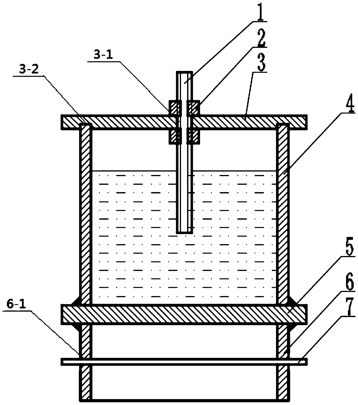
[0030] Specific implementation mode one: combine figure 1 Describe this embodiment, a kind of test device for measuring the cohesive force between bolt and ice of this embodiment, it comprises screw rod 1, nut 2, top cover 3, upper cylinder 4, partition plate 5, lower cylinder 6 and connecting pin 7, upper The cylinder 4 and the lower cylinder 6 are connected by a partition 5, and the upper cylinder 4 and the lower cylinder 6 are sealed and fixedly connected with the partition 5, the top cover 3 is installed on the upper cylinder 4, and the screw 1 is vertically installed on the The top cover 3 extends in the upper cylinder 4 , the screw 1 is screwed on the upper and lower ends of the top cover 3 through the nut 2 , and the connecting pin 7 is horizontally installed on the lower cylinder 6 .
[0031] Because water will expand with cold and shrink with heat during the freezing process, therefore, the upper cylinder 4 is made of Q235 steel.
[0032] In the present invention, th...
specific Embodiment approach 2
[0034] Specific implementation mode two: combination figure 1 To describe this embodiment, the center position of the top cover 3 of this embodiment is provided with a threaded through hole 3-1. With such a design, the screw rod 1 can pass through the top cover 3, and the measured length of the screw rod in water can be adjusted through the nut 2. Other components and connections are the same as those in the first embodiment.
specific Embodiment approach 3
[0035] Specific implementation mode three: combination figure 1 To describe this embodiment, an arc-shaped groove 1-2 is provided on the lower end surface of the top cover 3 of this embodiment. With such a design, it can be aligned with the center of the upper cylinder, ensuring that the screw is at the center of the ice during the freezing process, and the test results are more accurate and reliable; other components and connections are the same as those in the first or second embodiment.
PUM
| Property | Measurement | Unit |
|---|---|---|
| Bond strength | aaaaa | aaaaa |
Abstract
Description
Claims
Application Information