A battery box system and control method with high heat dissipation function

A battery box, high heat dissipation technology, applied in the direction of secondary batteries, battery pack components, secondary battery repair/maintenance, etc. Service life, improve heat dissipation effect, achieve consistent effect

Active Publication Date: 2021-06-15
中铁轨道交通装备有限公司
View PDF8 Cites 0 Cited by
  • Summary
  • Abstract
  • Description
  • Claims
  • Application Information

AI Technical Summary

Problems solved by technology

[0002] Now trams are gradually using lithium batteries with higher energy density and good environmental protection as power sources. Lithium batteries divide hundreds or even thousands of single batteries into several battery units, which are connected in series and in parallel to form high-voltage, For a high-current battery pack, dozens of single batteries for each battery unit are placed in a box. The battery emits a lot of heat during charging and discharging. If the heat cannot be discharged in a timely and uniform manner, it will affect the battery life and cause great security risks
[0003] At present, air cooling and liquid cooling are mainly used in the market. The air cooling method is prone to uneven heat dissipation and affects the consistency of the battery. The liquid cooling method just makes up for the defect of uneven air cooling.
In the liquid-cooled heat dissipation method, after the coolant passes through the pipeline, the internal liquid will not be stirred, resulting in a higher temperature of the coolant near the battery. The principle is that the temperature of the coolant is lower, and the effect of absorbing heat is reduced. Higher temperature leads to uneven temperature of the battery as a whole, and the battery is prone to damage and fire accidents

Method used


Image

  • A battery box system and control method with high heat dissipation function
  • A battery box system and control method with high heat dissipation function
  • A battery box system and control method with high heat dissipation function

Examples


Embodiment Construction

[0025] The present invention will be described in detail below with reference to the accompanying drawings.

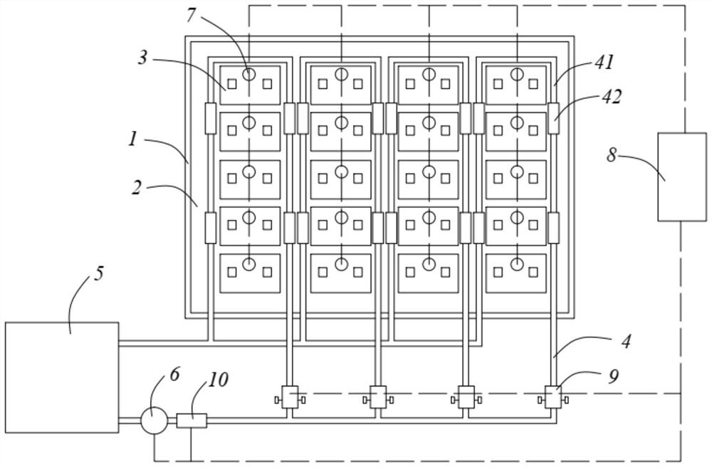
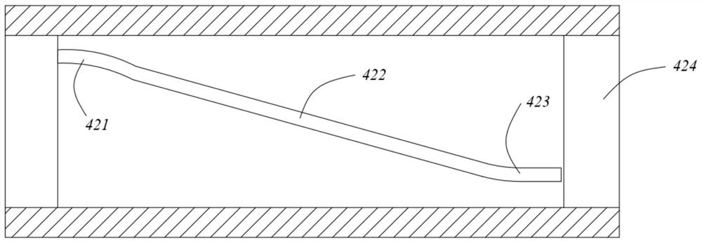
[0026] Such as figure 1 versus figure 2 A battery box system having a high heat dissipation function includes a battery case 1, a battery fixture 2 disposed within the battery case 1 and a number of unit cells disposed on the battery holder 2, and a number of The single battery 3 is divided into several battery packs in series, and several battery packs constitute a battery in parallel or in series, and the battery pack by each set is wound around the heat pipe 4, and the heat dissipating pipe 4 is a spiral disk wound disk around a single battery pack, at the same time The heat dissipation conduit 4 passes into a coolant, which is a calcium chloride solution; the heat dissipation pipe 4 is composed of a plurality of water pipe 41 and a plurality of joints 42 for connecting the water pipe 41, a water pipe 41 Between the connector 42, by the thread 424, the inner wall of the...


PUM


Abstract

The invention relates to a battery box system with high heat dissipation function and a control method, comprising a battery box body, a battery fixing part arranged in the battery box body, and a plurality of single batteries arranged on the battery fixing part, and the plurality of single batteries are divided into several For battery packs, heat dissipation pipes are coiled around each battery pack, and cooling liquid is passed into the heat dissipation pipes. The heat dissipation pipes are composed of several water pipes and several joints for connecting the water pipes. There is at least one spiral deflector on the inner wall of the joints. , the spiral deflector moves the liquid close to the battery away from the battery; a cooling water tank is installed next to the box, the heat dissipation pipe is connected to the cooling water tank to form a circuit, and a water pump is installed at the water outlet of the cooling water tank. The pipes are connected in parallel to the cooling water tank. The operation of the system is controlled by the BMS control unit to ensure the heat dissipation effect of the battery and the consistency of temperature.

Description

Technical field [0001] The present invention relates to the field of battery technology, in particular, to a battery box system and a control method having a high heat dissipation function. Background technique [0002] Now there is a high energy density, a lithium battery with a high energy density as a power supply, and the lithium battery is divided into several battery cells, skewers, and forming high pressure, and forms a high pressure after returning hundreds or even thousands of unit cells. The battery pack of the large current, the dozens of monomer batteries of each battery unit are placed in a box. The battery is released in a large amount of heat during the charge and discharge process, and the heat cannot be discharged in time, which will affect the battery life and exist. Safety hidden dangers. [0003] The market is mainly used in the market, and the liquid cooling is mainly used, and the air-cooled heat dissipation method is easy to generate heat dissipation is une...

Claims


Application Information

Patent Timeline
Patent Type & Authority Patents(China)
IPC IPC(8): H01M10/637H01M10/6567H01M10/613H01M10/48H01M10/42H01M50/249H01M50/258
CPCH01M10/637H01M10/613H01M10/6567H01M10/486H01M10/425H01M2010/4271H01M50/20Y02E60/10
Inventor 丁樱许峻峰罗冬冬董长杰朱震寰张松
Owner 中铁轨道交通装备有限公司
Why Eureka
Try Eureka