Parallel air-cooled battery box

A technology of battery box and parallel connection, which is applied in the field of electric vehicles to achieve the effect of ensuring temperature balance, improving lifespan and ensuring consistency

Pending Publication Date: 2017-07-25
SHANTOU UNIV
View PDF7 Cites 2 Cited by
  • Summary
  • Abstract
  • Description
  • Claims
  • Application Information

AI Technical Summary

Problems solved by technology

[0005] The purpose of the present invention is to provide a parallel air-cooled battery box to solve the problems of battery he

Method used


Image

  • Parallel air-cooled battery box
  • Parallel air-cooled battery box
  • Parallel air-cooled battery box

Examples


Embodiment Construction

[0029] The present invention will be further described below in conjunction with the accompanying drawings.

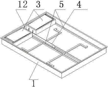
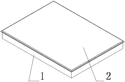
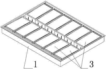
[0030] The structure of the present invention is as figure 1 , figure 2 , image 3 As shown, it includes a battery box cover 2 , a battery box body 1 , an air inlet duct 4 and a battery module 3 . The battery box cover 2 is set on the battery box body 1, and the bottom of the battery box body 1 is provided with a mounting bracket 5, and the structure of the mounting bracket is as follows: Figure 6 As shown, the side wall is provided with air inlet holes 11 and air outlet holes 12, such as Figure 5 As shown, the battery module 3 is set on the mounting bracket 5, such as Figure 4 shown. An air intake chamber is formed between the bottom of the battery box body 1 , the battery module 3 and the mounting bracket 5 . Such as Figure 7 As shown, the air inlet of the air inlet pipe 4 is connected to the air inlet hole 11 of the battery box body 1, the air inlet pipe...


PUM


Abstract

The invention relates to the field of electric vehicles and particularly relates to a parallel air-cooled battery box. The parallel air-cooled battery box comprises a battery box cover, a battery box body, an air inlet pipe and a battery module, wherein the battery box cover covers the battery box body; an installation bracket is arranged at the bottom of the battery box body; an air inlet hole and an air outlet hole are formed in the side wall; the battery module is arranged on the installation bracket; an air inlet chamber is formed among the bottom of the battery box body, the battery module and the installation bracket; an air inlet of the air inlet pipe is connected with the air inlet hole of the battery box body; the air inlet pipe passes through the installation bracket; an air outlet of the air inlet pipe is arranged in the air inlet chamber; the battery module comprises a module box body and a plurality of batteries in the module box body; air guide holes are formed in the upper end surface and the lower end surface of the module box body. The problems of heat dissipation of the batteries in the battery box, internal temperature balance of the battery module and temperature balance among battery modules are effectively solved, thereby prolonging the service life of a battery pack.

Description

technical field [0001] The invention relates to the field of electric vehicles, in particular to a parallel air-cooled battery box. Background technique [0002] With the development of society, new energy batteries have been widely promoted and used, and new energy vehicle technology is also developing rapidly. Limited by the loading space of new energy vehicles, batteries as the main energy storage components of vehicles are often closely arranged and connected in units of modules to ensure the power requirements of the entire vehicle. The compactly distributed battery modules generate a lot of heat during the operation of the vehicle, and the battery temperature rises significantly, which seriously shortens the battery life. At the same time, due to the inconsistent temperature rise of the batteries in the modules, the temperature rise between the modules is also different, which seriously affects the consistency of the batteries and ultimately shortens the service life ...

Claims


Application Information

Patent Timeline
IPC IPC(8): H01M2/10H01M10/613H01M10/6562H01M50/20H01M50/204
CPCH01M10/613H01M10/6562H01M50/20Y02E60/10
Inventor 彭雄斌张健李整陈方圆顾佩华
Owner SHANTOU UNIV
Why Eureka
Try Eureka