
Automatic cooling structure of automobile engine

An automotive engine, automatic cooling technology, applied in engine components, combustion engines, machines/engines, etc., can solve problems such as small application range, inability to maintain engine temperature balance, and inability to cool down.

Active Publication Date: 2021-04-09
兰陵县交通运输局
View PDF6 Cites 0 Cited by
  • Summary
  • Abstract
  • Description
  • Claims
  • Application Information

AI Technical Summary

Problems solved by technology

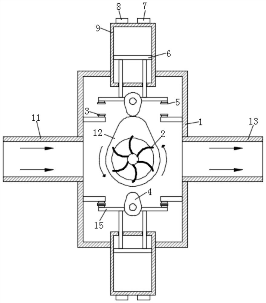
[0004] The purpose of the present invention is to solve the problem in the prior art that "the automobile engine is the heart of the automobile and plays an irreplaceable role in the operation of the automobile. In the process of using the existing automobile engine, the roads that the automobile walks are different, and the engine The power emitted is also different. The greater the power emitted by the engine, the more heat it generates, and the higher the temperature of the body. The existing engine cooling device cannot perform targeted cooling according to the temperature generated by the engine at different times, and cannot perform well. To maintain the temperature balance of the engine, the scope of application is small", thus proposing an automatic cooling structure for automobile engines

Method used


Image

  • Automatic cooling structure of automobile engine
  • Automatic cooling structure of automobile engine

Examples


Embodiment Construction

[0015] The following will clearly and completely describe the technical solutions in the embodiments of the present invention with reference to the accompanying drawings in the embodiments of the present invention. Obviously, the described embodiments are only some, not all, embodiments of the present invention.

[0016] In describing the present invention, it should be understood that the terms "upper", "lower", "front", "rear", "left", "right", "top", "bottom", "inner", " The orientation or positional relationship indicated by "outside", etc. is based on the orientation or positional relationship shown in the drawings, and is only for the convenience of describing the present invention and simplifying the description, rather than indicating or implying that the referred device or element must have a specific orientation, so as to Specific orientation configurations and operations, therefore, are not to be construed as limitations on the invention.

[0017] refer to Figure ...


PUM


Abstract

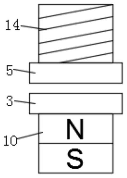
The invention discloses an automobile engine automatic cooling structure of an automobile engine. The automobile engine automatic cooling structure comprises a shell, a first ventilation pipeline and a second ventilation pipeline, wherein the first ventilation pipeline and the second ventilation pipeline are symmetrically and fixedly installed on the side wall of the shell, two liquid storage pipes are symmetrically and fixedly installed at the upper end and the lower end of the shell, all liquid storage pipes are fixedly installed in the shell, a cam is rotatably connected to the center position in the shell, fan blades are fixedly installed on the side wall of the front face of the cam and correspond to the first ventilation pipeline and the second ventilation pipeline, four connecting plates are symmetrically and fixedly installed on the inner wall of the shell, permanent magnets are fixedly installed on the side walls of the connecting plates, and first suction nozzles are fixedly installed at the ends, away from the corresponding connecting plates, of the permanent magnets. According to the automobile engine automatic cooling structure, targeted cooling can be conducted according to the temperatures generated by the engine at different moments, temperature balance of the engine can be well maintained, and the application range is wide.

Description

technical field [0001] The invention relates to the technical field of automobile engine cooling, in particular to an automatic cooling structure of an automobile engine. Background technique [0002] The car engine is the heart of the car, and plays an irreplaceable role in the operation of the car. When the existing car engine is in use, the power emitted by the engine is different depending on the road the car walks on. The bigger the engine, the more heat it generates, and the higher the temperature of the body. The existing engine cooling device cannot perform targeted cooling according to the temperature generated by the engine at different times, cannot maintain the temperature balance of the engine well, and has a small scope of application. [0003] In order to solve the above problems, the present invention proposes an automatic cooling structure for an automobile engine. Contents of the invention [0004] The purpose of the present invention is to solve the pro...

Claims


Application Information

Patent Timeline
Patent Type & Authority Applications(China)
IPC IPC(8): F01P9/02F01N5/02F04B17/00F04B17/03F04B53/16
CPCF01P9/02F01N5/02F04B17/00F04B17/03F04B53/16Y02T10/12
Inventor 鹿立勇
Owner 兰陵县交通运输局
Learn More