
Vehicle battery thermal management system

A battery thermal management and vehicle technology, applied in secondary batteries, circuits, electrical components, etc., can solve problems such as hindering the heat dissipation of the battery pack, slow heat dissipation, and insufficient heating or cooling performance of the battery pack in a timely and accurate manner. Timely and accurate cooling performance, simple structure effect

Active Publication Date: 2013-11-06
ZHEJIANG GEELY AUTOMOBILE RES INST CO LTD +1
View PDF5 Cites 1 Cited by
  • Summary
  • Abstract
  • Description
  • Claims
  • Application Information

AI Technical Summary

Problems solved by technology

This invention also has the following deficiencies: 1. This invention only considers the impact of the internal temperature of the battery pack on battery performance, and the external environmental factors only perform insulation treatment. Although the external insulating layer can block the temperature interference of the external environment on the battery pack to a certain extent, At the same time, it also hinders the battery pack's natural heat dissipation function in the air, blocking air circulation, and slow heat dissipation. The battery itself is a heating body during work. The valve is connected to the large and small cycles. When the solenoid valve is opened, the large and small cycles are carried out at the same time. The cooling or heating liquid of the small cycle will be directly absorbed by the coolant from the battery pack in the large cycle. The heat-up or cool-down performance of the battery pack is not timely and accurate; 3. The air-conditioning compressor system can be used for this refrigeration, but there is no detailed description of how to use the air-conditioning compressor system to connect the circulation system of the battery pack for refrigeration

Method used


Image

  • Vehicle battery thermal management system

Examples


Embodiment Construction

[0026] The following are specific embodiments of the present invention and in conjunction with the accompanying drawings, the technical solutions of the present invention are further described, but the present invention is not limited to these embodiments.

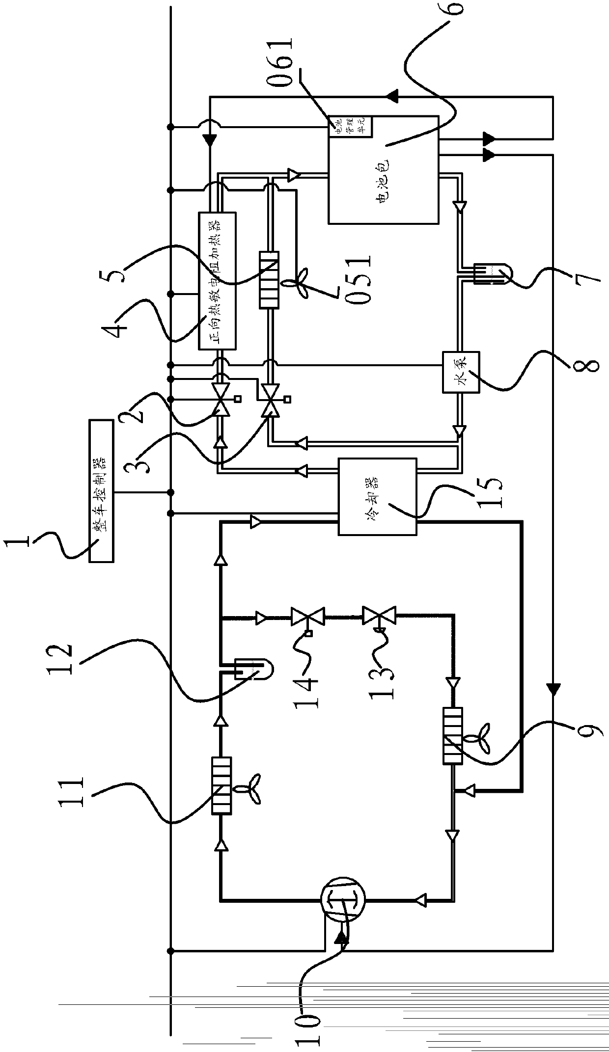
[0027] Such as figure 1As shown, the vehicle battery thermal management system includes a battery pack 6, a water tank 7, a water pump 8 and a radiator 5 to form a first liquid circulation circuit, and the first solenoid valve 3 on the first liquid circulation circuit is arranged on the water pump 8 and the heat dissipation circuit. Between the radiators 5, the radiator 5 is provided with a cooling fan 051 that accelerates the cooling speed. The battery pack 6 supplies power to the water pump 8, and a cooling structure and a heater 4 are sequentially connected between the water pump 8 and the battery pack 6 to form a second liquid circulation circuit, and the second solenoid valve 2 on the second liquid circulation circuit...


PUM


Abstract

The invention provides a vehicle battery thermal management system, and belongs to the technical field of automobile batteries. The vehicle battery thermal management system solves the problem that battery thermal management in the prior art is not accurate and timely and comprises a first liquid circulation loop, wherein the first liquid circulation loop consists of a battery pack, a water tank, a water pump and a radiator; a cooling structure and a heater are sequentially connected between the water pump and the battery pack to form a second liquid circulation loop; solenoid valves which only control respective liquid circulation loop are arranged on the first liquid circulation loop and the second liquid circulation loop; a temperature sensor is arranged on the battery pack; a battery management unit, the temperature sensor, the water pump, a first solenoid valve, a second solenoid valve, the cooling structure and the heater are connected with a complete vehicle controller; and the complete vehicle controller can receive a detection signal of the temperature sensor, process the detection signal, and send a control signal to control the operation of the water pump, the two solenoid valves, the cooling structure, the heater and the battery management unit. The system can accurately and timely judge a battery thermal environment and perform effective adjustment.

Description

technical field [0001] The invention belongs to the technical field of automobile batteries, and relates to a heat management system for an automobile battery. Background technique [0002] As the main energy storage element in electric vehicles, batteries are key components of electric vehicles and directly affect the performance of electric vehicles. Limited to the temperature conditions in different seasons in various regions of my country, electric vehicle power batteries need to withstand harsh environmental impacts such as high and low temperatures, which will shorten battery life and reduce battery performance. In general, if the temperature is lower than 0°C, charging the lithium battery will cause the separator to be punctured due to the precipitation of lithium ions, and a short circuit will occur; in addition, the discharge power and capacity of the battery will be affected when the temperature is too low, resulting in a significant decrease in vehicle performance...

Claims


Application Information

Patent Timeline
Patent Type & Authority Patents(China)
IPC IPC(8): H01M10/50H01M10/613H01M10/625H01M10/6567
CPCY02E60/12Y02E60/10
Inventor 李田田吴旭峰金启前由毅吴成明赵福全
Owner ZHEJIANG GEELY AUTOMOBILE RES INST CO LTD
Learn More