A new energy vehicle electrical system temperature control system and control method

A temperature control system, a technology for new energy vehicles, applied in battery/fuel cell control devices, electric vehicles, vehicle components, etc., can solve problems such as power drop, charge and discharge efficiency drop, traffic hidden dangers, etc., to achieve obvious use effect, reduce Low efficiency, the effect of improving efficiency

Active Publication Date: 2022-06-07
北创(山东)专用汽车制造有限公司
View PDF0 Cites 0 Cited by
  • Summary
  • Abstract
  • Description
  • Claims
  • Application Information

AI Technical Summary

Problems solved by technology

[0002] As a new travel tool vigorously advocated by the country, new energy vehicles have the characteristics of no pollution, high energy utilization efficiency, and good driving experience. New energy vehicles refer to vehicles powered by batteries or fuel engines and driven by electric motors. The power unit, electric motor are the same as the traditional fuel engine. The fuel engine, electric motor and battery system all need to have a reasonable working temperature. Small, but on the motor and battery, there will be a problem of power drop and charge and discharge efficiency drop due to small temperature changes, especially in high latitude and high altitude areas, because of the temperature, it will cause battery charging. The discharge efficiency drops a lot, making new energy vehicles parked on the road, which may seriously cause traffic hazards. In order to achieve better working efficiency of batteries and motors, a new energy vehicle electrical system temperature control system is hereby designed

Method used


Image

  • A new energy vehicle electrical system temperature control system and control method
  • A new energy vehicle electrical system temperature control system and control method
  • A new energy vehicle electrical system temperature control system and control method

Examples


Embodiment Construction

[0013] The present invention is further elaborated in further detail below in conjunction with the accompanying drawings and specific embodiments.

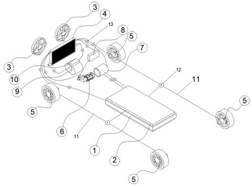
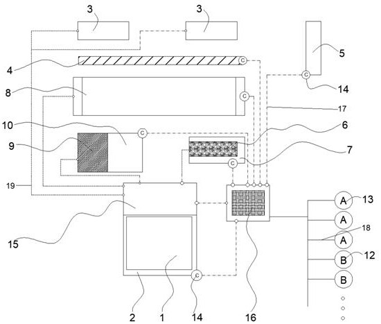
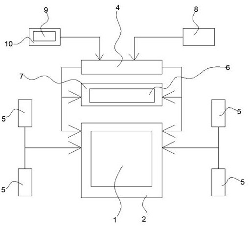
[0014]A new energy vehicle electrical system temperature control system, including battery system 1, battery temperature clip structure 2, cooling fan 3, water tank system 4, wheel heat recovery structure 5, motor 6, motor temperature control shell 7, air conditioning system 8, fuel engine 9, engine heat recovery structure 10, the battery temperature clip structure 2 is provided on the outside of the battery system 1, the cooling fan 3 is located on the outside of the water tank system 4, the motor temperature control shell 7 is located on the outside of the motor 6, The engine heat recovery structure 10 is located on the outside of the fuel engine 9, the battery temperature clip structure 2 is connected to the motor temperature control shell 7 through the temperature control line 11, the battery temperature clip structure 2 is connec...


PUM


Abstract

The invention relates to a temperature control system and a control method of a new energy vehicle electrical system, including a battery system, a battery temperature clamp structure, an air conditioning system, a fuel engine, and an engine heat recovery structure, the battery temperature clamp structure, a water tank system, and a wheel heat recovery structure The structure, motor temperature control shell, air conditioning system, and engine heat recovery structure are all equipped with temperature monitoring devices, and the battery system is equipped with an electric control structure and a temperature control data command structure. The invention optimizes the temperature control setting of the electric system of the new energy vehicle, improves it into a structure that recycles the heat of the vehicle, greatly reduces the low efficiency of the vehicle caused by overheating and overcooling, and switches through different valves and pumps The closed mode realizes different heat exchanges, keeps the battery system and the motor in a relatively stable and optimal working temperature environment, and improves the efficiency of the vehicle. The system adds facilities and does not occupy the space of the vehicle body. The use effect is obvious and should be promoted. .

Description

Technical field [0001] The present invention relates to the field of new energy vehicles, in particular to a new energy vehicle electrical system temperature control system and control method. Background [0002] New energy vehicles as a new travel tool vigorously advocated by the state, with no pollution, high energy utilization efficiency, good driving experience and other characteristics, new energy vehicles refer to the use of battery storage or fuel engine power supply, the use of motors to drive a kind of automotive power unit, the motor and the traditional fuel engine, fuel engine, motor, battery system need to have a more reasonable working temperature, the working temperature range of the fuel engine is larger, the general low temperature and high temperature on the fuel engine work efficiency is less impact , but in the motor and battery will appear because of a small temperature change, resulting in power decline, charging and discharging efficiency decline problem, es...

Claims


Application Information

Patent Timeline
Patent Type & Authority Patents(China)
IPC IPC(8): B60K1/00B60K11/04B60L58/26B60L58/27
CPCB60K1/00B60K11/04B60L58/26B60L58/27B60K2001/005B60K2001/006B60K2001/008Y02T10/70
Inventor 蒋学美
Owner 北创(山东)专用汽车制造有限公司
Why Eureka
Try Eureka