Volleyball serving device for volleyball training
A technology of serving device and volleyball, which is applied to sports accessories and other directions, can solve the problems of complicated operation, poor sparring effect, and difficulty in constantly controlling the force and speed of serving, and achieves the effect of high degree of automation and simple operation.
- Summary
- Abstract
- Description
- Claims
- Application Information
AI Technical Summary
Problems solved by technology
Method used
Image
Examples
Embodiment 1
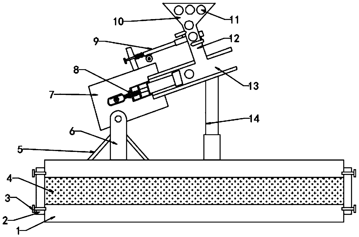
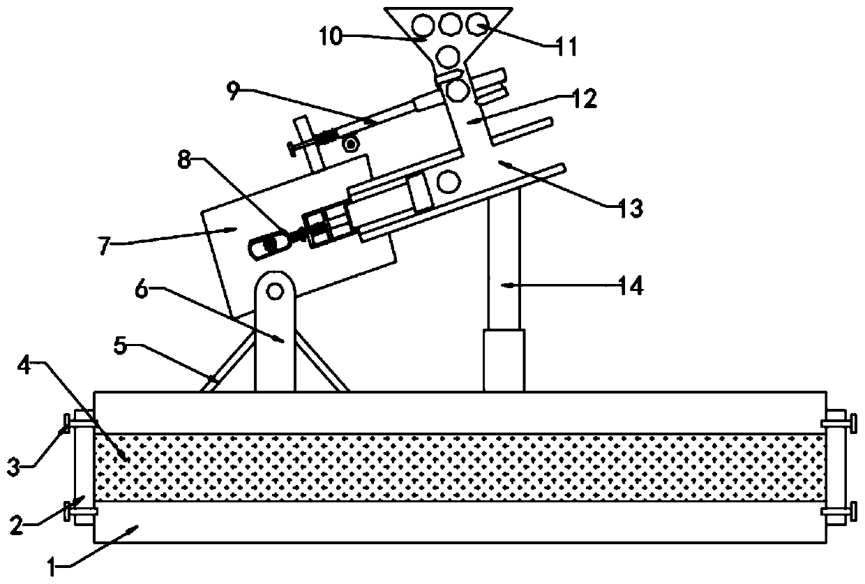
[0024] See figure 1 with figure 2 , In Embodiment 1 of the present invention, a volleyball serving device for volleyball training includes: a base 1, a bracket 6 is installed at the upper left end of the base 1, and both sides of the bracket 6 are reinforced and fixed by reinforcing ribs 5, and the bracket 6 The upper end is provided with a fixed box 7, the right side of the fixed box 7 is connected to the serving channel 13, the lower end of the serving channel 13 is connected with the upper end of the base 1 through the electric telescopic rod 14, the upper end of the serving channel 13 is connected to the ball outlet channel 12, and the upper end of the ball outlet channel 12 is provided There is a volleyball storage bucket 10, and a volleyball body 11 is placed inside the volleyball storage bucket 10;
[0025] A serving assembly 8 is installed on the right side of the fixed box 7, and the serving assembly 8 is connected to the serving passage 13; a serving assembly 9 is arran...
Embodiment 2
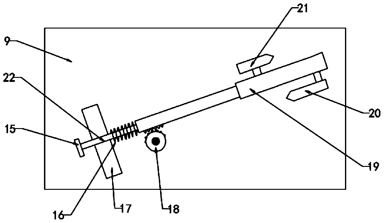
[0029] See image 3 Further, the ball outlet assembly 9 includes a worm 19 and a first movable rod 22. The upper and lower sides of the worm 19 are respectively provided with a first clamping block 20 and a second clamping block 21, the first clamping block 20 and the second clamping block 21 are all limited and movably installed inside the ball outlet passage 12. One end of the worm 19 is set outside the ball outlet passage 12, the other end of the worm 19 is connected to the first movable rod 22, and the lower end of the connection between the worm 19 and the first movable rod 22 is set There are saw teeth, the lower end of the saw teeth is engaged with the first half gear 18, and the drive shaft of the motor is installed inside the first half gear 18. Due to the beautiful effect of the drawing, the motor is not drawn in detail in the drawings of the manual;
[0030] Specifically, a first stopper 17 is provided at the upper end of the fixed box 7, and a first stopper 15 is provi...
Embodiment 3
[0034] See Figure 4 Further, the serving assembly 8 includes a piston 28, a first half gear 18, a second limiting block 29, a second movable rod 26, and an arc-shaped ring 23, and the piston 28 is limited to move inside the serving channel 13, and One end of the serving channel 13 is connected to the limiting groove 27, and the second limiting block 29 is arranged inside the limiting slot 27. Inside the limiting slot 27, one end of the second limiting block 29 is connected to the piston 28, and the second limiting block 29 is another One end is connected to the second movable rod 26, and one end of the second movable rod 26 passes through the limiting groove 27 and is connected to the arc ring 23 through the second compression spring 25;
[0035] Specifically, the arc ring 23 is provided with a second half gear 24 inside, and the second half gear 24 is connected to the drive shaft of the motor. Due to the drawing relationship, it is not drawn in detail in the drawings of the spe...
PUM
 Abstract
Description
Claims
Application Information
 - R&D
- Intellectual Property
- Life Sciences
- Materials
- Tech Scout
- Unparalleled Data Quality
- Higher Quality Content
- 60% Fewer Hallucinations
Browse by: Latest US Patents, China's latest patents, Technical Efficacy Thesaurus, Application Domain, Technology Topic, Popular Technical Reports.
© 2025 PatSnap. All rights reserved.Legal|Privacy policy|Modern Slavery Act Transparency Statement|Sitemap|About US| Contact US: help@patsnap.com


