Special Tooling for Clamping Cylinder Replacement of Quick Forging Manipulator and Its Replacement Method

A technology of clamping cylinder and manipulator, which is applied to workpiece clamping devices, manufacturing tools, etc., can solve the problems of safety threats to construction workers, easy occurrence of dislocation, hidden dangers, etc., so as to shorten maintenance time, improve work efficiency, and save manpower. Effect

Active Publication Date: 2021-02-26
上海五钢设备工程有限公司 +1
View PDF4 Cites 0 Cited by
  • Summary
  • Abstract
  • Description
  • Claims
  • Application Information

AI Technical Summary

Problems solved by technology

However, during construction, due to the unstable state of the inverted chain during use, it is easy to cause misalignment, which will affect the construction progress of the clamping cylinder reinstallation
At the same time, there are also great hidden dangers in safety. During the operation, once the clamping cylinder is separated from the rotary reducer of the fast forging manipulator, the clamping cylinder and the clamp arm with a self-weight of about 10 tons are in a state of falling at any time, which is enough to damage the construction work. Personnel pose a security threat

Method used


Image

  • Special Tooling for Clamping Cylinder Replacement of Quick Forging Manipulator and Its Replacement Method
  • Special Tooling for Clamping Cylinder Replacement of Quick Forging Manipulator and Its Replacement Method
  • Special Tooling for Clamping Cylinder Replacement of Quick Forging Manipulator and Its Replacement Method

Examples


Embodiment 1

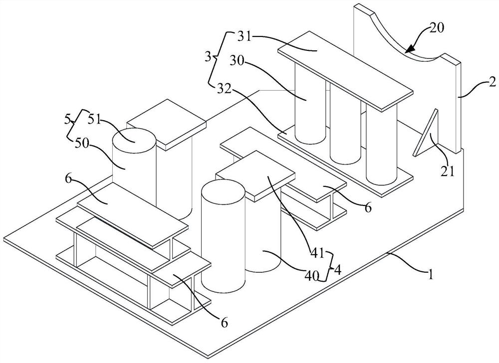
[0063] Such as Figure 1 to Figure 4 As shown, this embodiment provides a special tool for replacing the clamping cylinder of a fast forging manipulator, and the special tool includes:

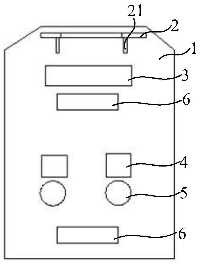
[0064] Bottom plate 1, fixed on the bottom plate 1 and sequentially arranged along the length direction of the bottom plate 1, the clamping cylinder support seat 2, the clamp rear end surface support seat 3, the clamp pin support seat 4, the clamping rod pin support seat 5;

[0065] The upper end surface 20 of the clamping cylinder support seat 2 is a downward arc-shaped end surface, and the arc-shaped size of the upper end surface 20 is adapted to the outer surface size of the clamping cylinder 7. The clamping cylinder support seat 2 is used for At the 7 parts of the support clamping cylinder;

[0066] The support base 3 at the end surface of the rear part of the clamp includes three first support columns 30 arranged at intervals along the width direction of the base plate 1, and is fixed o...

Embodiment 2

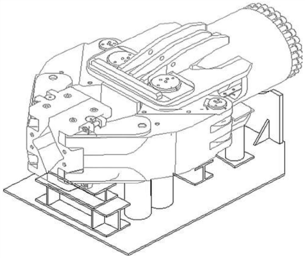
[0077] Such as Figure 5 and Figure 6 As shown, this embodiment provides a method for replacing the clamping cylinder of a fast forging manipulator, and the method for replacing the clamping cylinder at least includes the steps of:

[0078] 1) Lift the clamping cylinder replacement special tooling A of the fast forging manipulator described in Embodiment 1 to the center position in front of the clamp arm 11 of the fast forging manipulator 12 by using a crane before stopping the machine;

[0079] 2) Start the fast forging manipulator 12, place the clamp arm 11 on the clamping cylinder replacement special tooling A of the fast forging manipulator, and make sure that the clamp arm 11 is in the clamping cylinder replacement special tooling of the fast forging manipulator A's in-place state;

[0080] 3) Remove the connection between the clamping cylinder 13 and the rotary reduction box, and then move the fast forging manipulator 12 to separate the clamping cylinder 13 from the f...


PUM


Abstract

The invention discloses a special tool for replacing a clamping cylinder of a fast forging manipulator. The special tool comprises a bottom plate, a clamping cylinder supporting seat, a clamp rear endface supporting seat, a clamp bolt supporting seat and a clamping rod bolt supporting seat, wherein the clamping cylinder supporting seat, the clamp rear end face supporting seat, the clamp bolt supporting seat and the clamping rod bolt supporting seat are fixed to the bottom plate and sequentially arranged in the length direction of the bottom plate. In the disassembling and reassembling processof the clamping cylinder, the special tool is adopted to be matched with a travelling crane, the potential safety hazard caused to constructors due to the fact that an overweight clamp is fixed through a chain block is avoided, and the work of checking, replacing and the like of the clamping cylinder can be safely and conveniently implemented; compared with an existing clamping cylinder replacingmethod, a large amount of time for operating the chain block is shortened; in addition, the position of the special tool is fixed, a large amount of time for adjusting the mounting position can be shortened when the clamping cylinder is reassembled, manpower is saved, the maintenance time is shortened, and the operation efficiency is improved; and finally, the work of checking or replacing the clamp, a rotary speed reducer, a rotary bearing and other components can be achieved.

Description

technical field [0001] The invention belongs to the technical field of fast forging machine maintenance, and in particular relates to a clamping cylinder replacement special tool for a fast forging manipulator and a replacement method thereof. Background technique [0002] In the clamping cylinder replacement project of the fast forging manipulator, the construction workload is heavy and the operation time is long. The weight of the clamping cylinder is about 2T. When it is in the working position, the clamping cylinder is positioned by the steel structure of the main body of the quick forging manipulator and the supporting sprocket. When performing the task of replacing the clamping cylinder, the clamping cylinder must be moved out and connected with the fast forging manipulator. The body of the forging manipulator is disengaged. In this way, the clamping cylinder loses the steel structure of the original fast forging manipulator and the supporting positioning of the suppo...

Claims


Application Information

Patent Timeline
Patent Type & Authority Patents(China)
IPC IPC(8): B25B11/00
CPCB25B11/00
Inventor 唐孝国罗艳辉蔡辉君
Owner 上海五钢设备工程有限公司
Why Eureka
Try Eureka