Automatic stamping control system and method for printing terminal documents

A printing terminal and control method technology, applied to printing devices, printing, typewriters, etc., can solve problems such as large workloads, and achieve the effect of expanding the scope of application

Inactive Publication Date: 2020-02-14
南京鑫领越电子设备有限公司
View PDF5 Cites 0 Cited by
  • Summary
  • Abstract
  • Description
  • Claims
  • Application Information

AI Technical Summary

Problems solved by technology

[0002] In institutions such as school offices and large company offices, it is often necessary to affix stamps on printed paper in batches. The usual practice is to print out the documents and then stamp where they need to be stamped, but if there are many papers that need to be stamped , requires a lot of work, so there is an urgent need for a device that can automatically stamp while printing, or a device that can automatically stamp on printed paper

Method used


Image

  • Automatic stamping control system and method for printing terminal documents
  • Automatic stamping control system and method for printing terminal documents
  • Automatic stamping control system and method for printing terminal documents

Examples


Embodiment 1

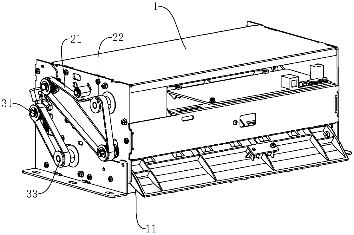
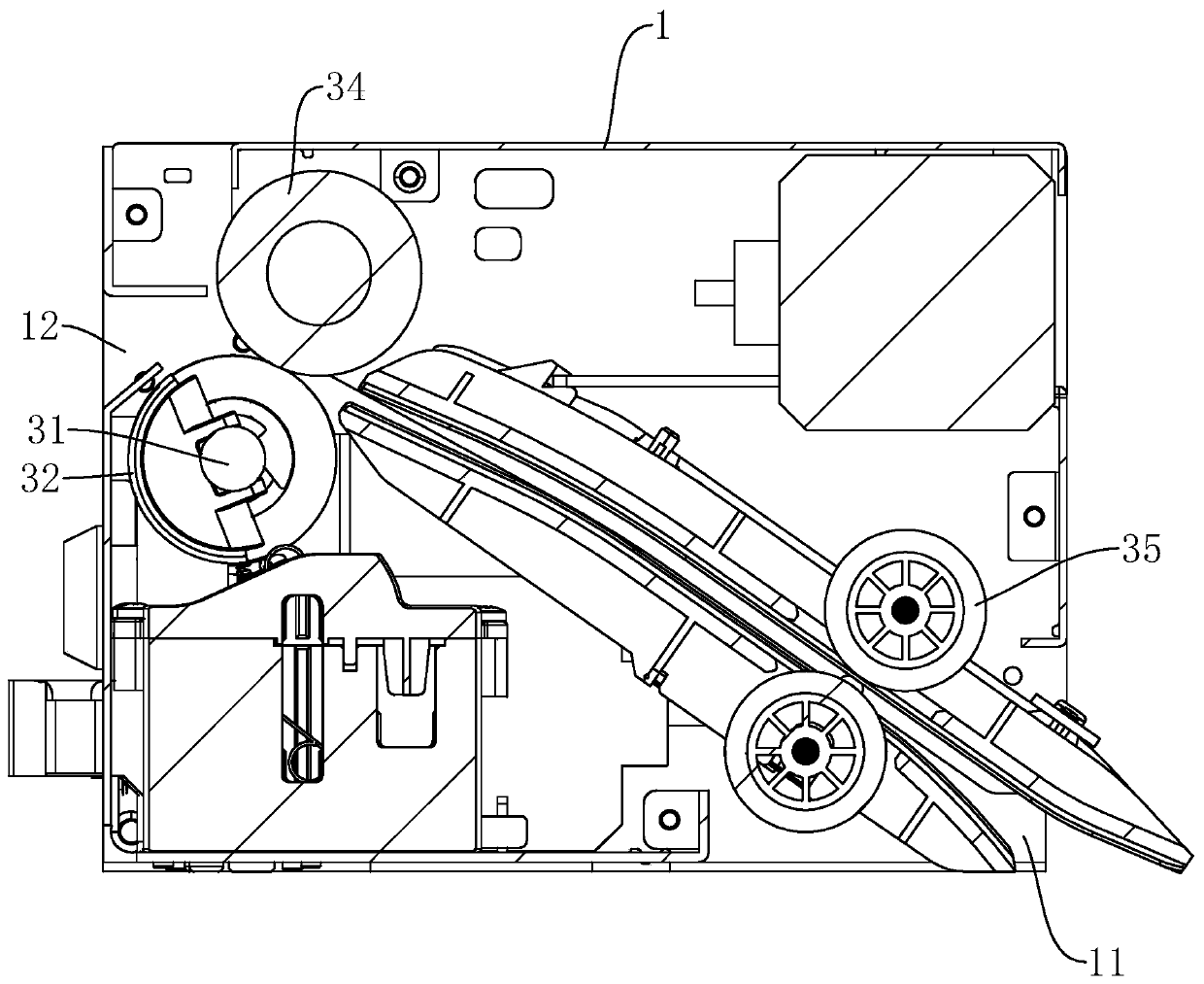
[0024] The invention discloses a printing terminal document automatic seal control system, referring to figure 1 , figure 2 and image 3 , including a casing 1, on which a paper inlet 11 and a paper outlet 12 are arranged. The casing 1 is placed on a matching printer, and the paper inlet 11 on the casing 1 is facing the paper outlet of the printer, so that the paper is sent from the printer into the paper inlet 11 by the short-distance driving force of the printer. The housing 1 is provided with a paper guiding mechanism near the paper inlet 11 to convey the paper to the paper outlet 12, and the housing 1 is provided with a stamping mechanism near the paper outlet 12 and sending the paper out of the paper outlet.

[0025] A sensor for sensing paper entering the casing 1 is fixed at the paper inlet 11, and the sensor is connected to a programmable logic controller, ie, a PLC, through wires. In this embodiment, the sensor may be a photoelectric sensor, and when the photoelec...

Embodiment 2

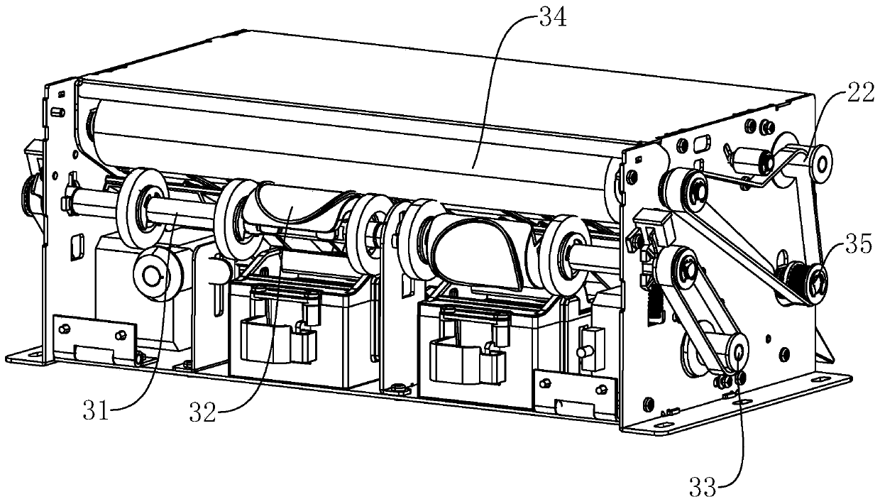
[0030] The invention discloses a control method for automatic stamping of a printing terminal document. Firstly, the short-distance driving force of the printer is used to send paper from the printer into the paper inlet 11. After the sensor detects the arrival of the paper, a trigger signal is sent to a programmable logic controller. . After the programmable logic controller receives the trigger signal sent by the sensor, it triggers the first drive mechanism 33 and the second drive mechanism 22 to start respectively, and the first drive mechanism 33 and the second drive mechanism 22 drive the rotating shaft 31, the platen roller 34 and the guide The paper roll 35 rotates. The paper guide roller 35 transmits the paper to the pressing roller 34, the paper enters between the pressing roller 34 and the rotating shaft 31, and the stamp 32 contacts the paper to complete the stamping.

[0031] Input constants in the programmable logic controller by computer, including the length d...


PUM


Abstract

The invention discloses an automatic stamping control system and method for printing terminal documents, relates to the technical field of printing and stamping and aims at solving the problems that in the prior art, paper which is stamped needs to be taken out from the upper portion of a shell manually, full automation cannot be achieved, and the efficiency is low. According to the technical scheme, a paper guiding mechanism is used for conveying paper towards a paper outlet is arranged at the position, close to the paper inlet, in the shell, and a stamping mechanism close to the paper outletis arranged in the shell; and a sensor capable of sensing the paper entering the shell is arranged at the position of the paper inlet and is connected with a programmable logic controller, the stamping mechanism comprises a rotating shaft provided with a stamp, the rotating shaft is connected with a motor, the programmable logic controller is used for controlling the motor, and therefore rotatingstarting and stopping and the rotating speed of the rotating shaft are controlled. By means of the automatic stamping control system and method for printing terminal documents, the batched automaticstamping effect is achieved.

Description

technical field [0001] The invention relates to the technical field of printing and stamping, in particular to a control system and method for automatic stamping of printing terminal documents. Background technique [0002] In institutions such as school offices and large company offices, it is often necessary to affix stamps on printed paper in batches. The usual practice is to print out the documents and then stamp where they need to be stamped, but if there are many papers that need to be stamped , requires a lot of work, so there is an urgent need for a device that can automatically stamp while printing, or a device that can automatically stamp on printed paper. Contents of the invention [0003] The object of the present invention is to provide a control system and method for automatic stamping of printing terminal documents, which has the effect of stamping in batches. [0004] Above-mentioned invention purpose of the present invention one is achieved by the followi...

Claims


Application Information

Patent Timeline
Patent Type & Authority Applications(China)
IPC IPC(8): B41K3/26B41K3/44B41K3/62B41J3/54B41J13/02B41J29/393
CPCB41J3/54B41J13/02B41J29/393B41K3/26B41K3/44B41K3/62
Inventor 不公告发明人
Owner 南京鑫领越电子设备有限公司
Why Eureka
Try Eureka