A louver ventilation device
A technology of ventilation device and louver, applied in the field of ventilation, can solve problems such as poor ventilation
- Summary
- Abstract
- Description
- Claims
- Application Information
AI Technical Summary
Problems solved by technology
Method used
Image
Examples
Embodiment
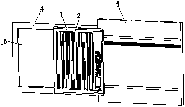
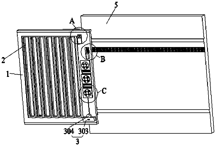
[0050] Such as figure 1 as shown, figure 1 It is a diagram of the working state of the louver ventilation device. The louver frame 1 is arranged on the wall 5 on the side of the window frame 4. A plurality of hollow louvers 2 are installed in the louver frame 1, and a plurality of hollow louvers 2 can be driven by gear 601 transmission. The louver frame 1 moves horizontally or vertically along the wall 5 to the window frame 4, and the part structure of the gear 601 is shown in figure 2 Partial enlarged view of region B.
[0051] As can be seen from the figure, it is the working state at this time, the louver frame 1 is arranged on the wall body 5 on the right side of the window frame 4, and has been driven to the glass sheet 10 on the left side.
[0052] Such as figure 2 as shown, figure 2 It is a schematic diagram of the structure of the louver ventilation device. The louver ventilation device includes a hollow louver 2, a louver frame 1, a ventilation device, a humidi...
PUM
 Abstract
Description
Claims
Application Information
 - R&D
- Intellectual Property
- Life Sciences
- Materials
- Tech Scout
- Unparalleled Data Quality
- Higher Quality Content
- 60% Fewer Hallucinations
Browse by: Latest US Patents, China's latest patents, Technical Efficacy Thesaurus, Application Domain, Technology Topic, Popular Technical Reports.
© 2025 PatSnap. All rights reserved.Legal|Privacy policy|Modern Slavery Act Transparency Statement|Sitemap|About US| Contact US: help@patsnap.com


