
Vacuumizing system and method for vacuum cabin of ramjet engine

A technology of ramjet and vacuum pumping system, which is applied in the direction of engine testing, machine/engine, jet engine testing, etc. It can solve the problems of limited ramjet test capability, inability to meet large flow conditions, and small vacuum working range, etc. Achieve the effect of saving test site, compact structure and maintaining stable vacuum degree

Active Publication Date: 2017-02-01
XIAN AEROSPACE PROPULSION TESTING TECHN INST
View PDF5 Cites 11 Cited by
  • Summary
  • Abstract
  • Description
  • Claims
  • Application Information

AI Technical Summary

Problems solved by technology

But this type of ejection device is only suitable for the situation where the incoming flow of the vacuum chamber is small and the vacuum degree is high. When the incoming flow of the vacuum chamber is large and the vacuum degree is not high, the capability of the secondary ejection device is not enough to extract The mixed gas of jet steam and primary working steam is all injected into the atmosphere, causing the gas blockage of the secondary inlet
This blockage will produce a "gasp" phenomenon, resulting in unstable pressure in the vacuum chamber, or even instantaneous overpressure, which brings risks to the test
[0004] At present, the capacity of the vacuum pumping system is only the maximum flow rate of 30kg / s to maintain the cabin pressure of 10-35kPa (absolute pressure). The vacuum pumping system cannot meet the large flow conditions
Therefore, although the first and second ejection devices are connected in parallel, although the suction vacuum is high, the working range is small, which seriously limits the test capability of the ramjet.

Method used


Image

  • Vacuumizing system and method for vacuum cabin of ramjet engine
  • Vacuumizing system and method for vacuum cabin of ramjet engine
  • Vacuumizing system and method for vacuum cabin of ramjet engine

Examples


Embodiment Construction

[0027] In order to solve the problem that the vacuum system of the vacuum chamber of the ramjet engine cannot meet the conditions of large flow. The invention provides a vacuum pumping system and method for a vacuum chamber of a ramjet engine.

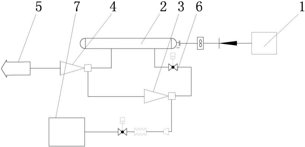
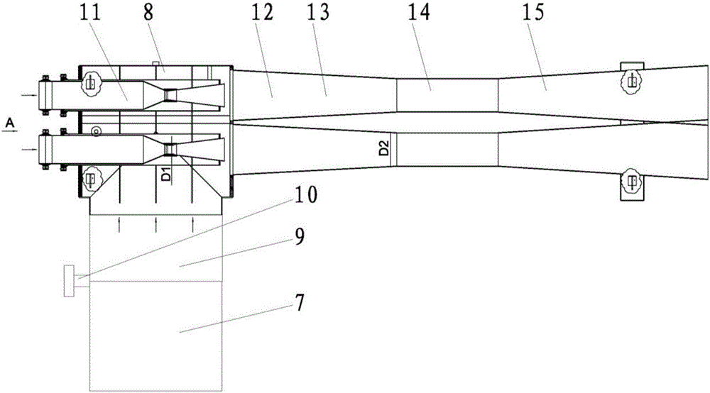
[0028] Such as figure 1 As shown, the system includes a steam source 1, a steam distributor 2, a primary injection device 3, a secondary injection device 4, a silencer tower 5 and a switching valve 6;

[0029] The primary injection device 3 and the secondary injection device 4 are connected in series, the steam inlet of the primary injection device 3 communicates with the steam distributor 2 through the switching valve 6; the steam inlet of the secondary injection device 4 is connected to the steam distributor 2 Communication; the steam outlet of the secondary ejection device 4 communicates with the external environment through the silencer tower 5; the vacuum inlet of the primary ejection device 3 communicates with the vacuum chamber...


PUM


Abstract

The invention belongs to the technical field of ramjet engine tests, and in particular relates to a vacuumizing system and a vacuumizing method for a vacuum cabin of a ramjet engine. The system comprises a vapor source, a vapor distributer, a first-stage ejection device, a second-stage ejection device, a muffling tower and a switch valve, wherein the first-stage ejection device and the second-stage ejection device are connected in series; a vapor inlet of the first-stage ejection device communicates with the vapor distributor through the switch valve; a vapor inlet of the second-stage ejection device communicates with the vapor distributor; a vapor outlet of the second-stage ejection device communicates with the external environment through the muffling tower; a vacuumizing inlet of the first-stage ejection device communicates with the vacuum cabin to be vacuumized; and the vapor distributor is connected with the vapor source. The system and the method, provided by the invention, have the advantages of large working range and high vacuumizing ability.

Description

technical field [0001] The invention belongs to the technical field of ramjet testing, and in particular relates to a vacuuming system and method for a ramjet vacuum chamber. Background technique [0002] When the ramjet engine is performing a high-altitude simulated test run, it is necessary to eject the exhaust gas generated by the engine in the vacuum cabin and the simulated high-temperature air from the incoming flow to the outside of the cabin to maintain a certain degree of vacuum in the cabin. If the required vacuum degree cannot be reached, the engine will hold pressure and the test will fail. [0003] At present, the vacuum system adopts a two-stage steam injection device connected in series for vacuuming, and the negative pressure generated by the injection nozzle of the first-stage ejection device injects the gas in the vacuum chamber into the first-stage pump, and the working The steam and ejection gas are sucked into the secondary pump by the negative pressure ...

Claims


Application Information

Patent Timeline
IPC IPC(8): F04F5/22F04F5/20F04F5/46F04F5/52G01M15/02G01M15/14
CPCF04F5/20F04F5/22F04F5/466F04F5/52G01M15/02G01M15/14
Inventor 史超赵建军邹伟龙陈聪李陆昊杜彬鱼凡超赵政社王广飚刘宏卫李谦翟文华
Owner XIAN AEROSPACE PROPULSION TESTING TECHN INST
Learn More