Dynamic calibration device for miniature ultrahigh pressure sensor

An ultra-high pressure and dynamic calibration technology, which is applied in the direction of measuring devices, measuring fluid pressure, instruments, etc., can solve the problems of increasing the use cost of sensors, limiting the popularization and application of sensors, and high calibration costs, so as to reduce the cost of dynamic calibration and realize small batches The effect of production, promotion and application

Inactive Publication Date: 2020-02-14
XI AN JIAOTONG UNIV
View PDF14 Cites 0 Cited by
  • Summary
  • Abstract
  • Description
  • Claims
  • Application Information

AI Technical Summary

Problems solved by technology

However, there are some disadvantages when this method is applied to miniature ultra-high pressure sensors: First, each batch of ultra-high pressure sensors should be sampled and dynamically calibrated, while the single-batch calibration cost of light gas guns is very high, which will undoubtedly increase The use cost of the sensor is reduced, and then the promotion and application of the sensor is limited; the second, the gun diameter of the light gas gun (the diameter of the flyer, the size of the target plate and the diameter of the gun are similar) is much larger than the size of the sensitive element of the miniature ultra-high pressure sensor, which will Make the pressure on the sensor approximate to the pressure at a certain point on the target plate
However, in practice, it is difficult to ensure that the impact load on the target plate is equal everywhere, so the pressure on the sensor is not equal to the pressure calculated according to the speed of the flyer, resulting in a certain error in the calibration curve

Method used


Image

  • Dynamic calibration device for miniature ultrahigh pressure sensor
  • Dynamic calibration device for miniature ultrahigh pressure sensor
  • Dynamic calibration device for miniature ultrahigh pressure sensor

Examples


Embodiment Construction

[0029] The present invention will be described in detail below in conjunction with the accompanying drawings.

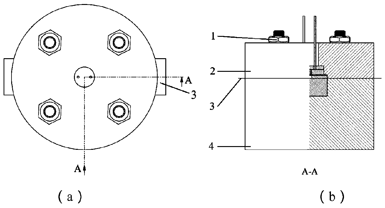
[0030] refer to figure 1 , a dynamic calibration device for a miniature ultra-high pressure sensor, comprising a target plate device 4, a miniature ultra-high pressure sensor 3 is fixed on the target plate device 4, a flyer drive device 2 is arranged above the miniature ultra-high pressure sensor 3, and the flyer drive The flyer output port of the device 2 is aligned with the sensitive element of the miniature ultra-high pressure sensor 3 , and the flyer driving device 2 and the target plate device 4 are connected by bolts 1 .

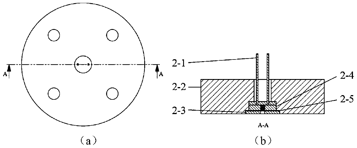
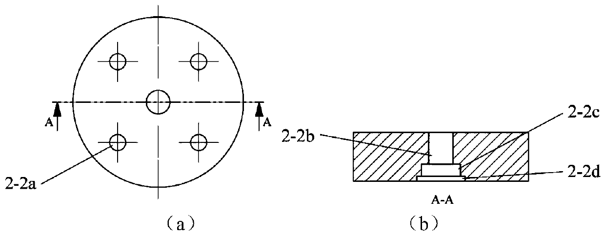
[0031] refer to figure 2 and image 3 , the flying piece driving device 2 includes a housing 2-2, the housing 2-2 is provided with a lead port 2-2b, a micro detonator limiting hole 2-2c and a flying piece limiting hole 2-2d, the micro detonator The limit hole 2-2c and the flyer limit hole 2-2d are made by precision machining, so that the ...


PUM

PropertyMeasurementUnit
diameteraaaaaaaaaa
thicknessaaaaaaaaaa

Abstract

The invention discloses a dynamic calibration device for a miniature ultrahigh pressure sensor. The dynamic calibration device comprises a target plate device. A miniature ultra-high pressure sensor is fixed on the target plate device. A flyer driving device is arranged above the miniature ultra-high pressure sensor; a flyer output port of the flyer driving device is aligned with a sensitive element of the miniature ultra-high pressure sensor; and the flyer driving device is connected with the target plate device through a bolt. The flyer driving device includes a housing; a micro detonator, aflyer and an acceleration chamber are sequentially fixed to the housing from top to bottom through a limiting hole structure. The target plate device includes a base; and a pressure bearing block isfixed to the base through the limiting hole structure. According to the invention, the miniaturization and thinning of the flyer are realized by adopting an MEMS process and thus the requirement thatthe size of the flyer is close to the size of a sensitive element of the miniature ultrahigh pressure sensor is met, thereby improving the precision of a dynamic calibration curve of the miniature ultrahigh pressure sensor. Moreover, the calibration device with low cost is suitable for dynamic calibration of the miniature ultrahigh pressure sensor.

Description

technical field [0001] The invention belongs to the technical field of pressure sensor testing, in particular to a dynamic calibration device for miniature ultra-high pressure sensors. Background technique [0002] With the continuous development of MEMS pyrotechnics, micro-nano energetic materials, etc., miniature ultra-high pressure sensors have been widely used in the characterization of the output performance of micro-scale charges. In order to ensure a certain test accuracy, the dynamic calibration of the miniature ultra-high pressure sensor has become a key problem to be solved urgently. [0003] Among the existing ultra-high pressure sensor calibration methods, light gas cannon loading is the most commonly used calibration method. Its basic principle is: the flying pieces in the light gas cannon are accelerated in the launch tube and hit the target plate. Shock waves are generated in the target plate, so that a pressure acts on the sensor. At the same time, a test sy...

Claims


Application Information

Patent Timeline
Patent Type & Authority Applications(China)
IPC IPC(8): G01L25/00G01L27/00
CPCG01L25/00G01L27/00
Inventor 张国栋刘元赵玉龙韦学勇张一中王馨晨李慧任炜
Owner XI AN JIAOTONG UNIV
Why Eureka
Try Eureka