Control circuit for vehicle LED display lamp

An LED display lamp and control circuit technology, applied in the control field, can solve the problems of increasing the number of constant current drive circuits and increasing the circuit cost, and achieve the effect of reducing the circuit cost and reducing the number of MCU pins.

Pending Publication Date: 2020-02-14
上海摩特尼克汽车科技有限公司
View PDF0 Cites 0 Cited by
  • Summary
  • Abstract
  • Description
  • Claims
  • Application Information

AI Technical Summary

Problems solved by technology

[0004] See attached figure 2 , each LED needs a constant current drive circuit to make it work in the constant current mode. When the number

Method used


Image

  • Control circuit for vehicle LED display lamp
  • Control circuit for vehicle LED display lamp
  • Control circuit for vehicle LED display lamp

Examples


Embodiment Construction

[0024] The specific implementation of the vehicle LED display lamp control circuit of the present invention will be described in detail below in conjunction with the accompanying drawings.

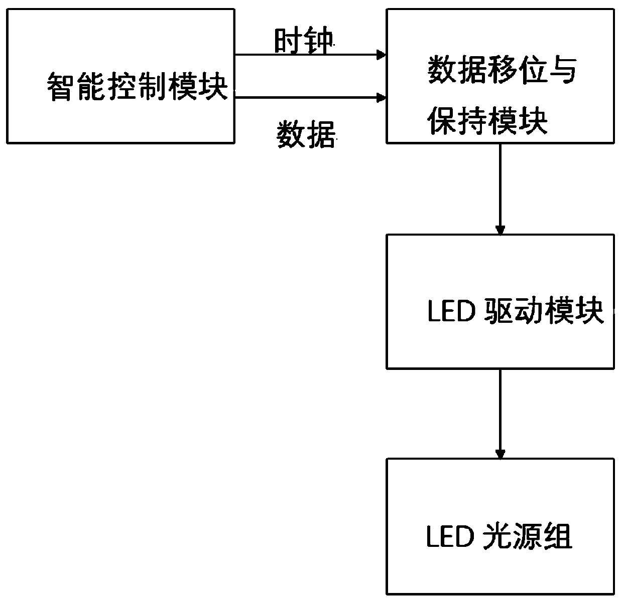
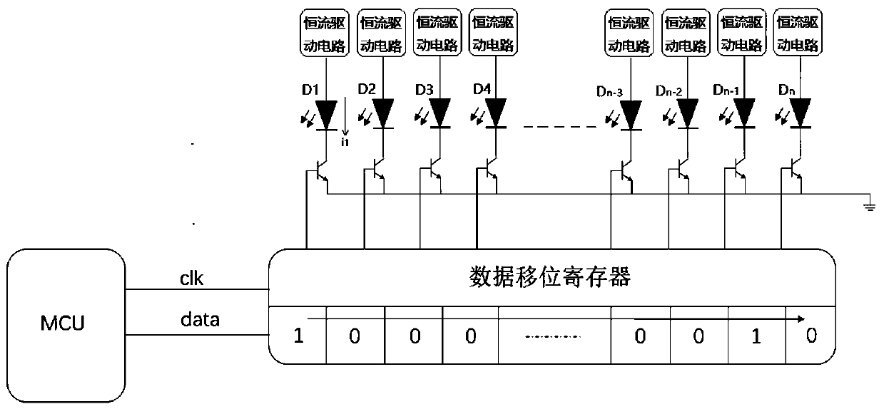
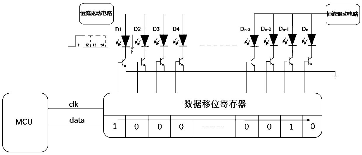
[0025] See attached figure 1 , 3 , the vehicle LED display light control circuit includes a control signal generation module, a data shift and hold module, an LED drive module and an LED light source group; the control signal generation module is used to generate the first clock signal (clk1 in the figure) and data signal, and transmit it to the data shift and hold module; the data shift and hold module is used to perform data shift on the data signal according to the clock signal, and generate a driving control signal and send it to the LED driver module; the LED driving module is used to drive corresponding LED lamps in the LED light source group to light up according to the driving control signal.

[0026] The LED drive module is at least one constant current drive circuit, each const...


PUM


Abstract

The invention relates to the field of control technology, and discloses a control circuit for vehicle LED display lamp, which comprises a control signal generating module, a data holding module, an LED driving module and an LED light source group. The LED driving module is at least one constant current driving circuit. Each constant current driving circuit is connected to multiple LED lamps in theLED light source group. The constant current driving circuit conducts a plurality of connected LED lamps in a time-sharing manner. According to the invention, only one LED is driven by a constant current driving circuit in a very short period of time, and each LED is cyclically driven in turn, so that the constant current circuit is decreased and the cost is greatly reduced.

Description

technical field [0001] The invention relates to the technical field of control, in particular to a vehicle LED display lamp control circuit. Background technique [0002] See attached figure 1 With the wide application of LED lighting technology in automobiles, the use of LEDs for dynamic lighting displays in automobiles is becoming more and more popular. For example, water-type turn signals and ambient lights. The system is generally composed of multiple LEDs, and the control system lights up each LED according to the time and order set by the program, thereby forming a dynamic display effect. The system generally consists of an intelligent control module, a data shift and hold module, an LED driver module and an LED light source group. [0003] Among them, the intelligent control module is generally composed of MCU. The data shift and hold module is to reduce the requirement on the number of MCU input and output pins. Because if multiple LEDs are directly controlled b...

Claims


Application Information

Patent Timeline
IPC IPC(8): H05B45/30
CPCY02B20/40
Inventor 刘兴岭
Owner 上海摩特尼克汽车科技有限公司
Why Eureka
Try Eureka