linear actuator

A technology of linear actuators, actuators, applied in transmissions, beds, sofas, etc.

Active Publication Date: 2021-10-26
LINAK AS
View PDF16 Cites 0 Cited by
  • Summary
  • Abstract
  • Description
  • Claims
  • Application Information

AI Technical Summary

Problems solved by technology

[0006] However, the use of such snap locks requires additional components and additional steps when mounting the rear mount to the axle of a portion of the bed

Method used


Image

  • linear actuator
  • linear actuator
  • linear actuator

Examples


Embodiment Construction

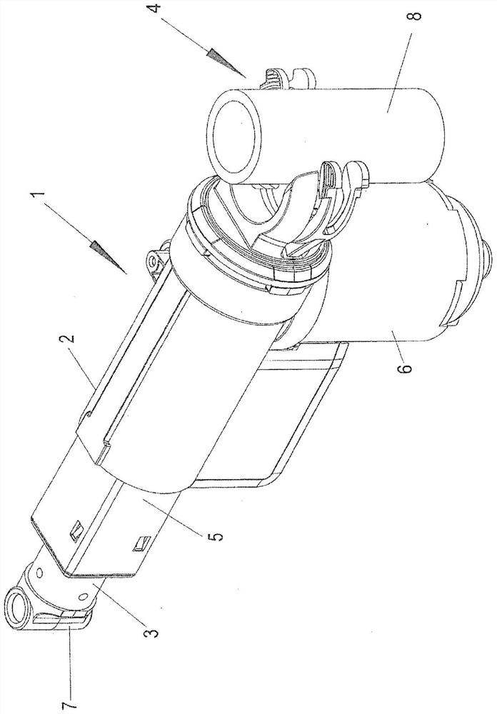
[0032] figure 1 A linear actuator 1 is shown comprising a support frame 2 , a driven element 3 movable at the front end of the support frame 2 and a mount 4 at the rear end of the support frame 2 .

[0033] The driven element 3 is a so-called "inner tube" that is telescopic inside an outer tube 5 connected to the support frame 2 . An electric motor 6 is connected to the support frame 2 and drives a spindle arranged in the support frame 2 and the outer tube 5 . The driven element 3 is connected to a spindle nut which is threaded on the spindle. The spindle nut is secured against rotation. When the motor 6 drives the spindle, the spindle nut and thus the driven element 3 is driven out of or into the outer tube 5 . The direction of movement of the driven element 3 depends on the direction of rotation of the electric motor 6 .

[0034] The driven element 3 is connected to a front mount 7 which can be used to connect the driven element 3 to eg a part of a bed.

[0035] A mount...


PUM


Abstract

A linear actuator is described comprising an actuator housing, a driven element movable at the front end of the linear actuator and a mount at the rear end of the linear actuator ( 4), wherein said mount (4) comprises two arms (9, 10) and a housing space (11) between said two arms (9, 10). The object on which the present invention is based is to provide a linear actuator which can be easily mounted by means of its rear mounting. To this end, at least one arm (9, 10) is provided with a lever (12, 13) rotatable about an axis between an open position and a closed position, wherein in said closed position said lever (12, An end portion (14, 16) of 13) at least partially closes an opening (18) between said two arms (9, 10) and enables access to said opening (18) in said open position.

Description

technical field [0001] The present invention relates to a linear actuator comprising an actuator housing, a driven element movable into and out of the front end of the linear actuator and a A mount, wherein the mount includes two arms and an accommodating space between the two arms. Background technique [0002] Such a linear actuator is known, for example, from EP 2 975 297 A2. The mount is used to connect the linear actuator to an element by which the one element is to be moved relative to the other element. [0003] A wide application of such linear actuators is for use in beds. When the linear actuator is activated, it adjusts eg the backrest portion or the leg rest portion of the bed. [0004] A mount at the rear end of the linear actuator (also referred to as a "rear mount") is connected to a portion of the bed via a shaft. Furthermore, the driven element at the front end of the linear actuator is connected to another element of the bed. [0005] In the linear act...

Claims


Application Information

Patent Timeline
Patent Type & Authority Patents(China)
IPC IPC(8): A47C20/04F16H25/20
CPCA47C20/041F16H25/20F16H2025/2037F16H2025/2084
Inventor M·克努森H·斯科比R·索伦森
Owner LINAK AS
Why Eureka
Try Eureka