Unlock instant, AI-driven research and patent intelligence for your innovation.

An automatic loading and unloading machine for turning bar-shaped threaded parts

A technology for automatic loading and unloading and threaded parts, which is applied in the direction of automatic entry/exit of workpieces, thread cutting machines, metal processing machinery parts, etc. It can solve the problems of parts quality impact, inconvenient hand-holding, low efficiency, etc., to prevent scratches and bumps Injury, reduce manual intervention, reduce the effect of risk

Active Publication Date: 2020-09-11
罗帮亮
View PDF7 Cites 0 Cited by
  • Summary
  • Abstract
  • Description
  • Claims
  • Application Information

AI Technical Summary

Problems solved by technology

[0002] Turning is a very common processing method of mechanical parts. When the parts are turned, they need to be loaded and unloaded. However, when ordinary people manually load and unload, there will be certain dangers, and artificial loading and unloading Operation, the efficiency is very low and the cost is high, especially after the processing of some parts, the surface temperature of the parts will be particularly high, and it is not convenient to hold by hand. The surface of the part is damaged, which has a great impact on the quality of the part

Method used


Image

  • An automatic loading and unloading machine for turning bar-shaped threaded parts
  • An automatic loading and unloading machine for turning bar-shaped threaded parts
  • An automatic loading and unloading machine for turning bar-shaped threaded parts

Examples


Embodiment Construction

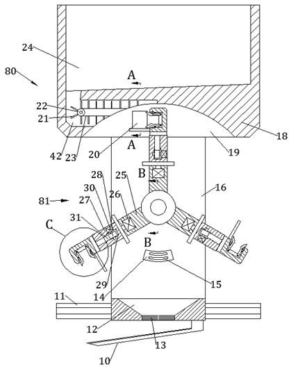
[0016] Combine below Figure 1-4 The present invention is described in detail, wherein, for the convenience of description, the orientations mentioned below are defined as follows: figure 1 The front, back, left, right, up, and down directions of the view direction are the same, figure 1 It is the front view of the device of the present invention, figure 1 The directions shown are consistent with the front, back, left, right, up, and down directions of the front view direction of the device of the present invention.

[0017] refer to Figure 1-4 , according to an embodiment of the present invention, an automatic loading and unloading machine for turning bar-shaped screw parts, including a fixed seat 11 fixedly installed on a lathe, on which a support rod 16 is slidably installed, and the top surface of the support rod 16 is The material box 18 is fixedly installed on the top, and the material box 18 is provided with a conveying device 80 that can transport raw materials. Th...


PUM


Abstract

The invention discloses an automatic loading and unloading machine for machine-turned rod-shaped screw elements. The automatic loading and unloading machine for the machine-turned rod-shaped screw elements comprises a fixed seat fixedly arranged on a turning lathe, wherein a support rod is slidably arranged on the fixed seat; a work bin is fixedly arranged on the top surface of the support rod; raw materials to be processed are orderly placed in a storage space, and the raw materials in the storage space can roll into a conveying channel; a first motor is started to drive a conveying cylinderto rotate, the conveying cylinder pulls a conveyor belt to move, and the conveyor belt drives a push plate to feed the raw materials into a feed inlet, so that manual operation can be replaced; the machine-turned screw elements can be directly and automatically clamped, loaded and unloaded, so that the manual intervention can be remarkably improved, the risk during work is reduced, and the processing rate is increased; and the automatic loading and unloading machine for the machine-turned rod-shaped screw elements is applicable to various machine tools, simple in structure and wide in use range.

Description

technical field [0001] The invention relates to the field of turning processing, in particular to an automatic loading and unloading machine for turning bar-shaped screw parts. Background technique [0002] Turning is a very common processing method of mechanical parts. When parts are turned, they need to be loaded and unloaded. However, when ordinary people manually load and unload, there will be certain dangers, and artificial loading and unloading Operation, the efficiency is very low, and the cost is high, especially after the processing of some parts, the surface temperature of the parts will be particularly high, and it is not convenient to hold by hand. Bumping the surface of a part has a great impact on the quality of the part. Contents of the invention [0003] The object of the present invention is to provide an automatic loading and unloading machine for turning bar-shaped screw parts, which is used to overcome the above-mentioned defects in the prior art. [...

Claims


Application Information

Patent Timeline
Patent Type & Authority Patents(China)
IPC IPC(8): B23B15/00B23G1/44B23G11/00B23Q7/00B23Q7/04B23Q7/06B23Q7/08
CPCB23G1/44B23G11/00B23Q7/00B23Q7/003B23Q7/04B23Q7/06B23Q7/08B23Q2707/003B23Q2707/006
Inventor 朱敬坤
Owner 罗帮亮