
Method for effectively removing dust of printer

A technology for printers and dust, applied in printing devices, printing, etc., can solve the problem of low efficiency in cleaning dust

Inactive Publication Date: 2020-02-18
成都优迅奇科技有限公司
View PDF9 Cites 0 Cited by
  • Summary
  • Abstract
  • Description
  • Claims
  • Application Information

AI Technical Summary

Problems solved by technology

[0004] The purpose of the present invention is to provide a method that can effectively clean the dust of the printer. By setting the connecting block in the box, the matching groove on the connecting block is used to cooperate with the installation block, and the movable plate that is convenient to rotate is set on the top of the box. It is used to block the installation hole, and then use the movable fixed rod to limit the rotation of the movable plate. When disassembling and assembling, it is only necessary to control the position of the fixed rod, which solves the problem of low efficiency in cleaning dust

Method used


Image

  • Method for effectively removing dust of printer
  • Method for effectively removing dust of printer
  • Method for effectively removing dust of printer

Examples


Embodiment 1

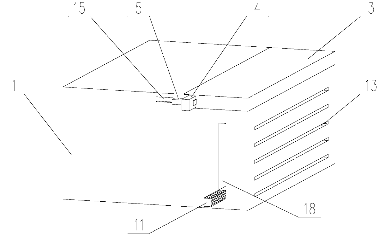
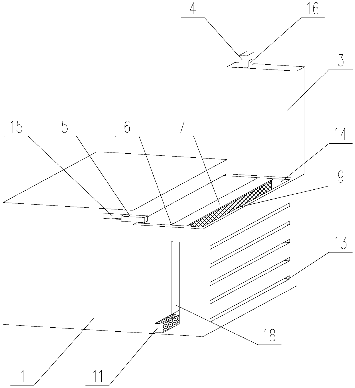
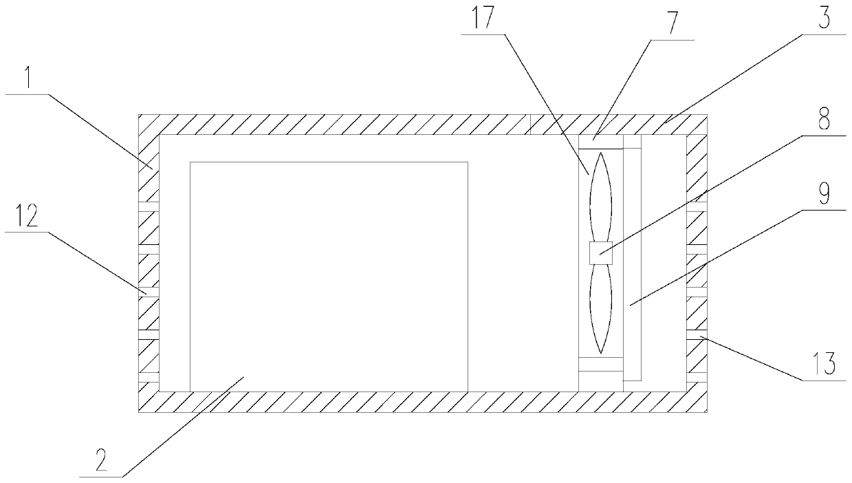
[0039] A method for effectively cleaning printer dust, comprising a box body 1 and a printer body 2 placed inside the box body 1, and air inlets 13 and air outlets communicating with the inside of the box body are respectively provided on both sides of the box body 1 12. A dust removal device is provided between the printer main body 2 and the air inlet 13, and the dust removal device includes a movable plate 3, a movable block, a fixed rod 5, a matching block 4, a connecting block 6, an installation block 7, and a fan device 8 and dust filter 9,

[0040] An installation hole 14 is provided on the top surface of the box body 1 away from the printer body 2, the bottom of the installation hole 14 communicates with the inside of the box body 1, and one end of the movable plate 3 is connected to the end surface of the installation hole 14. One side is hinged, the hinge axis between the movable plate 3 and the box body 1 is parallel to the ground, the movable plate 3 covers the ins...

Embodiment 2

[0051] A specific implementation description is made for the operation mode in Embodiment 1.

[0052] Such as figure 2 As shown, in the present invention, a fixed plate 10 is provided inside the box body 1, and the control rod 11 passes through the side wall of the box body 1 to connect with the fixed plate 10. The user can push the control rod 11 along the movable groove 18 to control the fixed plate. 10, use the fixed plate 10 to control the position of the installation block 7. When the installation block 7 needs to be taken out, the user can clamp it from the side where the installation block 7 is in contact with the side wall of the box body 1, so as to avoid taking out the installation block 7. To be in contact with the dust-proof net 9, causing the dust to fall inside the casing 1, it is inconvenient to clean up.


PUM


Abstract

The invention provides a method for effectively removing dust of a printer. A box body and a printer body put in the box body are included. A mounting hole is formed in the side, away from the printerbody, of the top face of the box body, the hole bottom of the mounting hole communicates with the interior of the box body, one end of a movable plate is hinged to one side of the end face of the mounting hole, the mounting hole in the box body is covered with the movable plate, a guide groove is formed in the side face of the box body, the movable block cooperates with the guide groove, a cooperation block is connected with the side, away from the hinge end, of the movable plate, a limiting through hole is formed in the side face of the cooperation block, one end of a fixing rod communicateswith the limiting through hole, the other end of the fixing rod is connected with the movable block, a connecting block is connected with the inner wall, provided with the guide groove, of the box body, a cooperation groove is formed in the side face, away from the inner wall of the box body, of the connecting block, the mounting block is mounted in the box body, one side of the mounting block cooperates with the cooperation groove, and the other side of the mounting block makes contact with the inner wall, away from the connecting block, of the box body. The problem that the working efficiency of dust removing is not high is solved.

Description

technical field [0001] The invention relates to the field of printers, in particular to a method capable of effectively cleaning printer dust. Background technique [0002] A printer is one of the output devices of a computer, which is used to print computer processing results on related media. When the printer is working, it is necessary to continuously carry out heat dissipation work to avoid overheating and damage to the internal electrical devices, which will affect the normal operation of the printer. [0003] But because the shell of the printer is provided with holes for ventilation and heat dissipation, dust can easily enter the inside of the shell. If dust enters the casing, it is easy to cause a short circuit. Although there is usually a dust filter at the air inlet, which can intercept most of the dust particles, the particles with smaller diameters will pass through the dust filter. The hole is attached to the fan or blown away directly. As time goes by, there...

Claims


Application Information

Patent Timeline
Patent Type & Authority Applications(China)
IPC IPC(8): B41J29/12
CPCB41J29/12
Inventor 刘娟
Owner 成都优迅奇科技有限公司
Learn More