
Automatic control device of belt conveying device

A technology of equipment automation and control device, which is applied to conveyor control devices, conveyors, conveyor objects, etc., can solve the problems of irregular material placement, affect transportation, and cannot meet the needs of use, and achieve quantitative unloading and conveying. Effect

Inactive Publication Date: 2020-02-18
SUZHOU DESIMIER SMART TECH CO LTD
View PDF0 Cites 8 Cited by
  • Summary
  • Abstract
  • Description
  • Claims
  • Application Information

AI Technical Summary

Problems solved by technology

[0004] The object of the present invention is to provide an automatic control device for belt conveying equipment to solve the problem that the existing belt conveying equipment cannot ensure that the conveying trough is under the feeding pipe when feeding, and cause the material to swing when feeding. Irregularity or detachment from the conveyor belt, which affects the transportation, reduces the transmission efficiency, and cannot meet the needs of use

Method used


Image

  • Automatic control device of belt conveying device
  • Automatic control device of belt conveying device
  • Automatic control device of belt conveying device

Examples


Embodiment Construction

[0020] The following will clearly and completely describe the technical solutions in the embodiments of the present invention with reference to the accompanying drawings in the embodiments of the present invention. Obviously, the described embodiments are only some, not all, embodiments of the present invention.

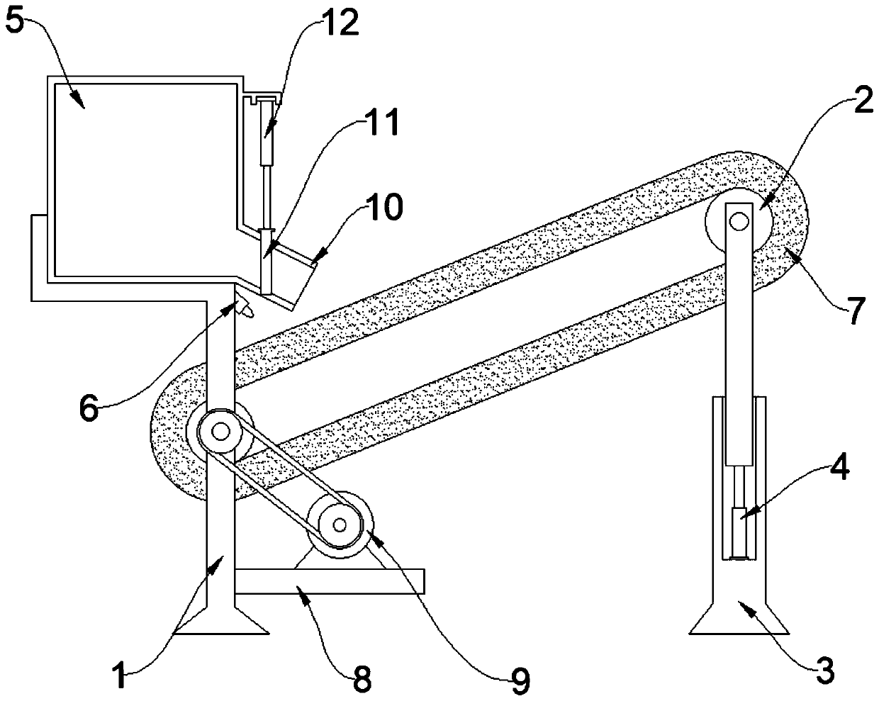
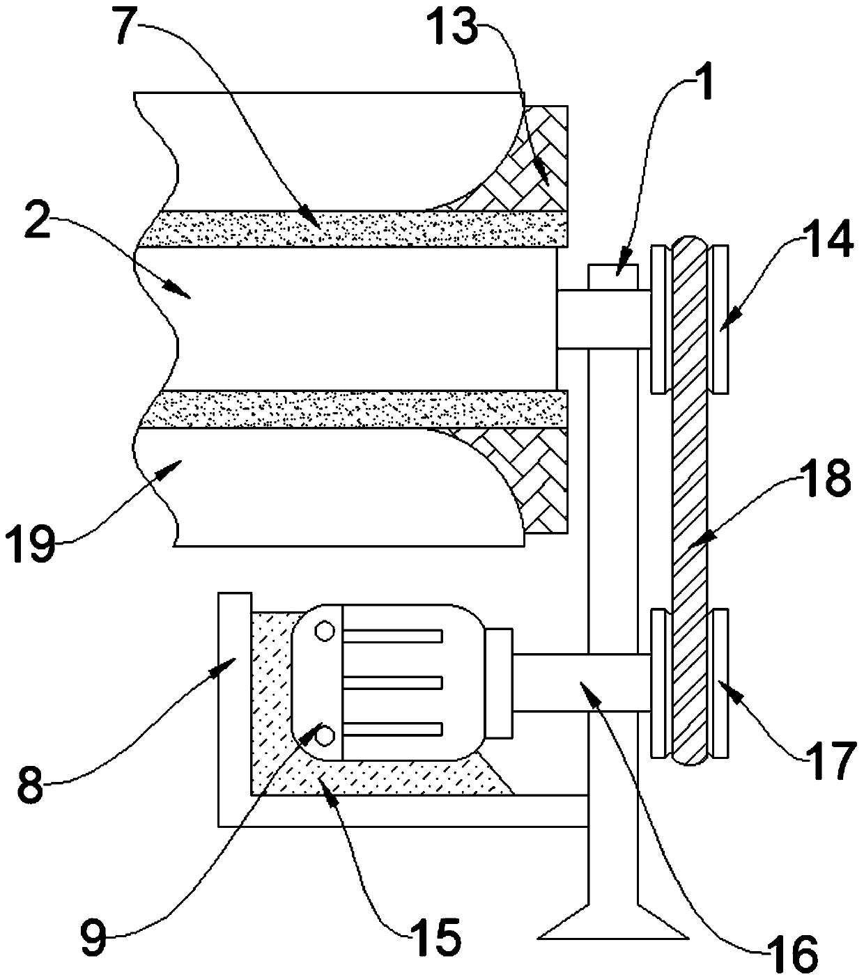
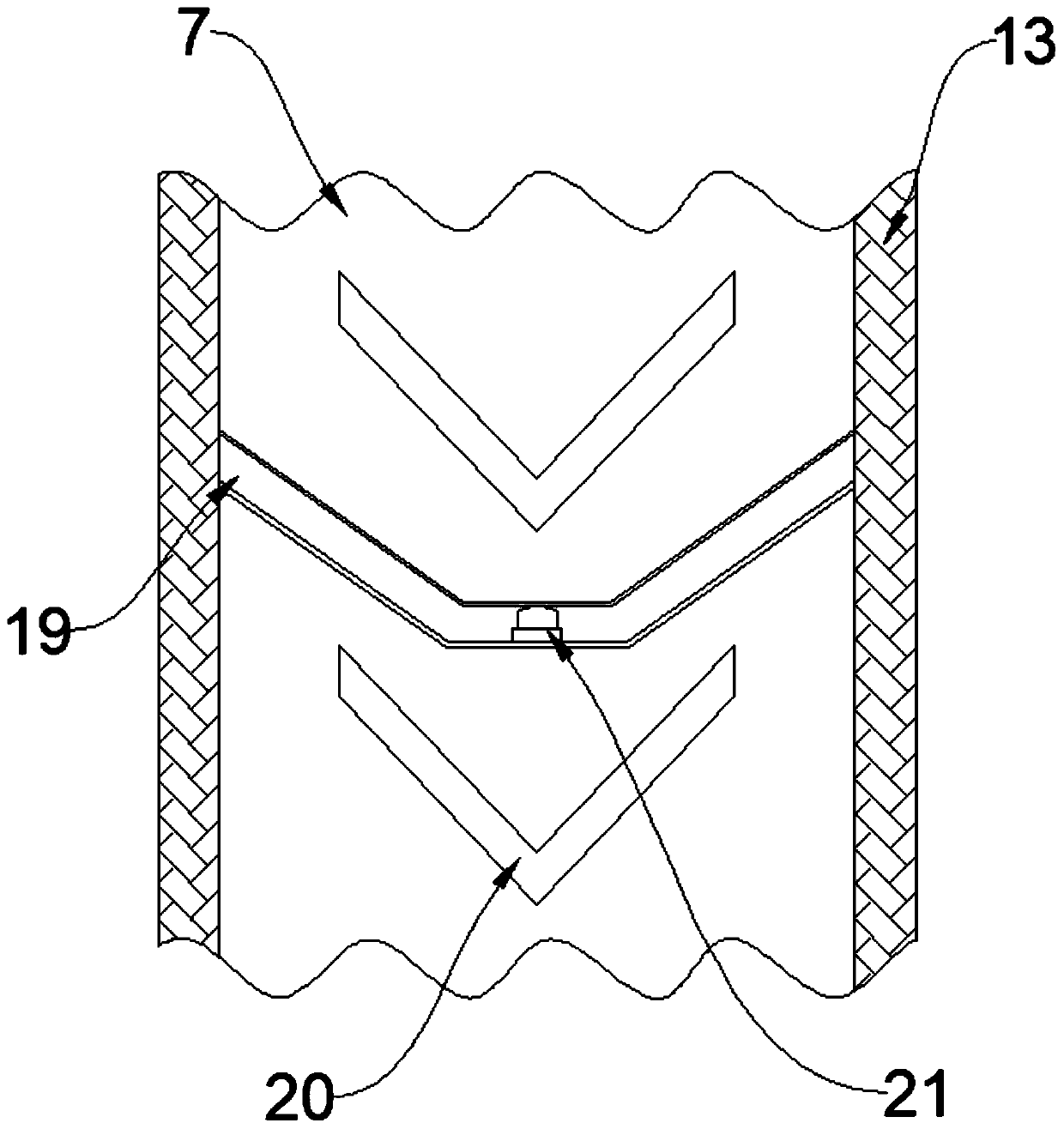
[0021] see Figure 1-4 , an embodiment provided by the present invention: an automatic control device for belt conveying equipment, including a support frame 1, a lifting seat 3 is arranged below the support frame 1, and one end of the support frame 1 extends to the inside of the lifting seat 3, Conveying roller 2 is arranged between support frame 1, and conveying roller 2 is provided with two, and two conveying rollers 2 are connected with support frame 1 in rotation, and conveying belt 7 is arranged between two conveying rollers 2, and conveying belt 7 and The conveying roller 2 is connected by transmission, a supporting plate 8 is provided on one side of the suppo...


PUM


Abstract

The invention discloses an automatic control device of a belt conveying device and relates to the technical field of automatic control conveying. The automatic control device aims at solving the problems that an existing belt conveying device cannot ensure that a conveying groove is located below a discharging pipe during discharging, materials are not placed in a standard manner or disengage fromthe conveying belt during feeding, and conveying is affected. A lifting seat is arranged below one supporting frame, conveying rollers are arranged between the supporting frames, a conveying belt isarranged between the two conveying rollers, a supporting plate is arranged on one side of one supporting frame, a servo motor is arranged above the supporting plate, a driven wheel is arranged on oneside of the conveying roller, and a rotating shaft is arranged on one side of the output end of the servo motor. A drive wheel is arranged on one side of the rotating shaft, a discharging bin is arranged above the supporting frame, a discharging pipe is arranged on one side of the discharging bin, and a second electric telescopic rod is arranged on one side of the discharging bin. Limiting platesare arranged at the outer portion of the conveying belt, and a dividing plate is arranged between the two limiting plates.

Description

technical field [0001] The invention relates to the technical field of automatic control conveying, in particular to an automatic control device for belt conveying equipment. Background technique [0002] A belt conveyor is a friction driven machine that transports material in a continuous manner. It is mainly composed of frame, conveyor belt, idler roller, roller, tensioning device, transmission device and so on. It can form a material conveying process from the initial feeding point to the final unloading point on a certain conveying line. It can not only transport broken materials, but also transport finished items. In addition to pure material transportation, it can also cooperate with the requirements of the technological process in the production process of various industrial enterprises to form a rhythmic assembly line. Widely used in home appliances, electronics, electrical appliances, machinery, tobacco, injection molding, post and telecommunications, printing, f...

Claims


Application Information

Patent Timeline
Patent Type & Authority Applications(China)
IPC IPC(8): B65G43/08B65G47/19B65G23/22B65G23/04B65G21/12
CPCB65G21/12B65G23/04B65G23/22B65G43/08B65G47/19B65G2203/042
Inventor 周军周皓
Owner SUZHOU DESIMIER SMART TECH CO LTD
Learn More