Casting molded large compressor cylinder block pickup machine

A compressor cylinder block and casting molding technology, which is applied in the field of compressor manufacturing, can solve problems such as boom deformation, heavy weight, and boom breakage, and achieve the effects of avoiding thread deformation damage, improving stability, and avoiding cylinder tilting

Active Publication Date: 2020-02-18
浙江象睿机电设备有限公司
View PDF7 Cites 3 Cited by
  • Summary
  • Abstract
  • Description
  • Claims
  • Application Information

AI Technical Summary

Problems solved by technology

[0004] The present invention provides a machine for taking parts after casting and forming of a large compressor cylinder body, aiming to solve the following problems when using the lifting tool in the prior art to take parts and hoist the large compressor cylinder body: (1) The mass of the large compressor cylinder is relatively heavy. When the studs on the sling and the screw holes on the cylinder cooperate with each other, the gap between the threads in the screw holes of the cylinder and the threads on the sling studs after the cylinder is hoisted It will generate a large vertical extrusion force, which will easily cause thread damage and deformation, and affect the later assembly of the cylinder; (2) Due to the heavy weight of the cylinder of a large compressor, as long as the cylinder is lifted slightly, it will A large lateral load is generated on the boom, causing deformation of the boom, and even causing the breakage of the boom

Method used


Image

  • Casting molded large compressor cylinder block pickup machine
  • Casting molded large compressor cylinder block pickup machine
  • Casting molded large compressor cylinder block pickup machine

Examples


Embodiment Construction

[0029] The embodiments of the present invention will be described in detail below with reference to the accompanying drawings, but the present invention can be implemented in many different ways defined and covered by the claims.

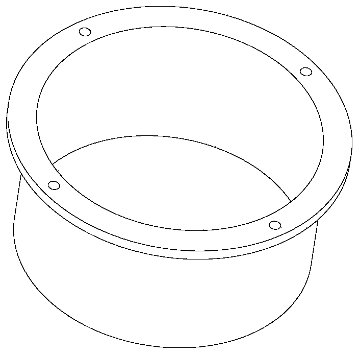
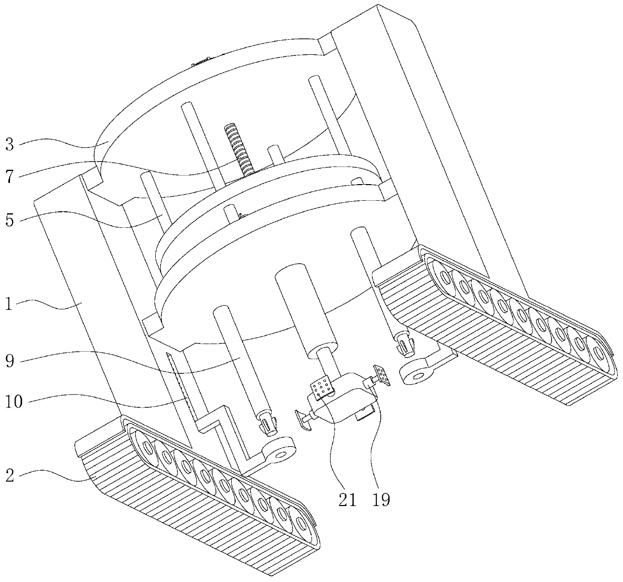
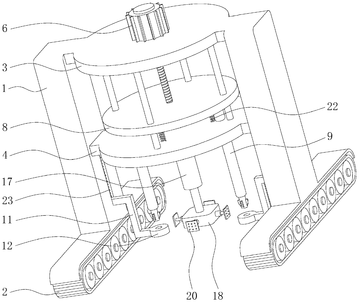
[0030] figure 1 shows a compressor cylinder such as Figure 2 to Figure 6 As shown, this embodiment provides a method for figure 1 The shown large-scale compressor cylinder block pick-up machine includes two parallel mounting columns 1, and the bottom of the mounting columns 1 is fixedly equipped with track wheels 2. A cylindrical first mounting platform 3 is fixed horizontally between the tops of the two mounting columns 1 , and a second mounting platform 4 having the same shape and size as the first mounting platform 3 is fixed horizontally between the middle parts of the two mounting columns 1 . Several guide rods 5 are vertically fixedly installed between the first installation platform 3 and the second installation platform 4 . The middle po...


PUM


Abstract

The invention belongs to the technical field of compressor manufacturing and specifically relates to a casting molded large compressor cylinder block pickup machine. The casting molded large compressor cylinder block pickup machine comprises mounting columns and crawler wheels. A first mounting table and a second mounting table are mounted between the mounting columns. Guide rods and a lead screware arranged between the two mounting tables. A rotation motor is mounted on the top surface of the first mounting table and is fixedly connected with the lead screw. A lifting platform is arranged between the mounting tables. The bottom surface of the lifting platform is provided with a lifting rod. The mounting columns are provided with sliding grooves. Bearing brackets are arranged in the sliding grooves in a matched mode. The bearing brackets are fixedly connected with bearing blocks. The bearing blocks are internally provided with through holes. The bottom of the outer sidewall of each lifting rod is sunken inwards to form a step and is provided with a plurality of accommodating grooves. A limiting block is hinged to the interior of each accommodating groove. Each limiting block is fixedly connected with a first spring. When the casting molded large compressor cylinder block pickup machine is used for picking up and hoisting a large compressor cylinder block, no vertical acting force is generated between threads in screw holes of the cylinder block and the lifting rods, and the situation of thread deformation damage is avoided.

Description

technical field [0001] The invention belongs to the technical field of compressor manufacturing, and in particular relates to a machine for taking parts after casting and forming a cylinder body of a large compressor. Background technique [0002] The compressor cylinder is the key part of the compressor and is usually cast. After casting, the cylinder body needs to be taken out from the mold for surface finishing treatment. The Chinese invention patent with the application number CN201910039880.6 shows a hoisting tool for hoisting a cylinder block, including a main lifting ring, a boom and a bottom plate. One end of the boom is connected to the main lifting ring, and the other end is connected to the middle of the bottom plate. Both ends are provided with a plurality of bolt holes corresponding to the positions of the screw holes on the cylinder block. Spreader screws are inserted into the bolt holes. The spreader screws include nuts, studs and movable shafts. Connected i...

Claims


Application Information

Patent Timeline
Patent Type & Authority Applications(China)
IPC IPC(8): B66F7/14B66F7/28
CPCB66F7/14B66F7/28
Inventor 霍修沛李健
Owner 浙江象睿机电设备有限公司
Why Eureka
Try Eureka