
Asphalt laying device

An asphalt and equipment technology, applied in the field of asphalt laying equipment, can solve the problems of easy solidification, slowness, reduced asphalt forming and mixing efficiency, etc., and achieve the effects of rapid discharge and simple equipment structure

Inactive Publication Date: 2020-02-18
齐嘉蕾
View PDF0 Cites 2 Cited by
  • Summary
  • Abstract
  • Description
  • Claims
  • Application Information

AI Technical Summary

Problems solved by technology

[0002] Asphalt is used in road paving. Since asphalt is made of a mixture of various materials, the mixed asphalt is poured when paving the road, and the mixed asphalt is poured onto the road surface, and then rolled into shape by some rolling equipment. Form a fixed road surface, because the temperature of the asphalt drops during the dumping process, the asphalt will be poured slowly, and in more serious cases, there will be more problems, such as: due to the drop in the temperature of the asphalt in general dumping equipment, the use of conveyors Asphalt is conveyed in a form, because there is a gap between the conveyors, the asphalt mixture falls from the gap inside the conveyor during transportation, either falling to the area that does not need to be paved, or additionally falling to increase the asphalt content in the paved area , as we all know, more asphalt content will make the road molding incomplete, and the existing asphalt mixture is poured slowly after mixing, so that the temperature of the asphalt is lowered when it is waiting to be transported out, so that the equipment is not suitable for the formation and mixing of asphalt. Reduced efficiency, easy to solidify

Method used


Image

  • Asphalt laying device
  • Asphalt laying device
  • Asphalt laying device

Examples


Embodiment Construction

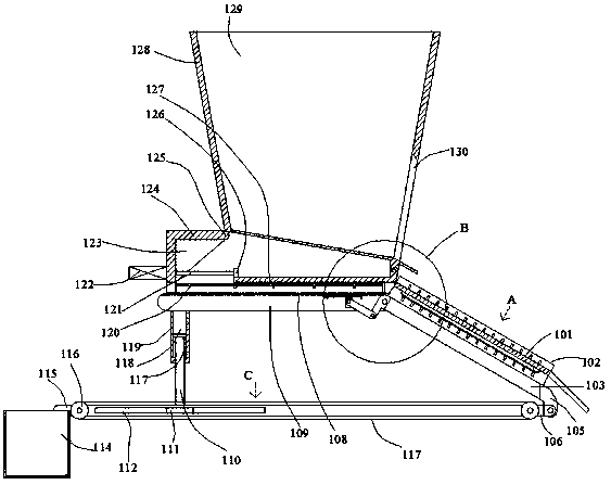
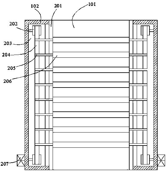
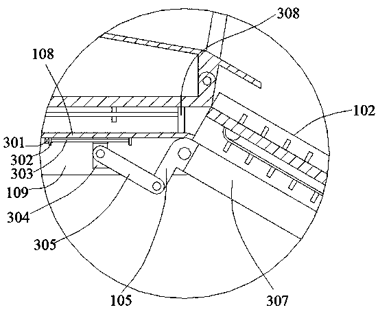
[0022] like Figure 1-Figure 4 As shown, the present invention is described in detail. For the convenience of description, the orientations mentioned below are now stipulated as follows: figure 1 The up, down, left, right, front and back directions of the projection relationship are the same. A kind of asphalt laying equipment of the present invention includes a top box 108, an open cavity 109 is arranged in the top box 108, and the upper end surface of the top box 108 is fixed. There is a top support block 124, an open cavity 123 is arranged in the top support block 124, and an opposite seat 308 fixed to the top box body 108 is arranged on the right side of the top support block 124, and the opposite side An extension rod 120 is fixed between the seat body 308 and the end wall of the cavity 123, a dome 125 is fixed on the right end surface of the top support block 124, and a useful For the shaking device that loads asphalt and shakes the asphalt out, the lower side of the sh...


PUM


Abstract

The invention discloses an asphalt laying device. The asphalt laying device comprises a top box body, wherein an open accommodating cavity is formed in the top box body; a top supporting block is fixedly arranged on the upper end surface of the top box body; an open accommodating cavity is formed in the top supporting block; an opposite side seat body fixed to the top box body is arranged on the right side of the top supporting block; an extension rod is fixedly arranged between the opposite side seat body and the end wall of the accommodating cavity; a dome is fixedly arranged on the right end surface of the top supporting block; and a shaking device used for loading asphalt and shaking out the asphalt is arranged on the upper sides of the top supporting block and the top box body. The asphalt laying device is simple in structure, adopts the design of various devices, realizes rapid discharge of the asphalt, avoids retention of the asphalt, enables the asphalt to be poured more efficiently, and can collect redundant falling asphalt to achieve the purpose of energy conservation.

Description

technical field [0001] The invention relates to the technical field of asphalt paving equipment, in particular to asphalt paving equipment. Background technique [0002] Asphalt is used in road paving. Since asphalt is made of a mixture of various materials, the mixed asphalt is poured when paving the road, and the mixed asphalt is poured onto the road surface, and then rolled into shape by some rolling equipment. Form a fixed road surface, because the temperature of the asphalt drops during the dumping process, the asphalt will be poured slowly, and in more serious cases, there will be more problems, such as: due to the drop in the temperature of the asphalt in general dumping equipment, the use of conveyors Asphalt is conveyed in a form, because there is a gap between the conveyors, the asphalt mixture falls from the gap inside the conveyor during transportation, either falling to the area that does not need to be paved, or additionally falling to increase the asphalt cont...

Claims


Application Information

Patent Timeline
Patent Type & Authority Applications(China)
IPC IPC(8): E01C19/18
CPCE01C19/182
Inventor 齐嘉蕾
Owner 齐嘉蕾
Learn More