
Reservoir spillway and flood discharge method

A spillway and reservoir technology, applied in the spillway field, can solve the problems of shaft damage and high maintenance costs, and achieve the effect of reducing impact force and reducing the possibility of damage

Active Publication Date: 2020-02-18
深圳市东深工程有限公司
View PDF6 Cites 0 Cited by
  • Summary
  • Abstract
  • Description
  • Claims
  • Application Information

AI Technical Summary

Problems solved by technology

[0004] But similar to the above-mentioned spillway in the actual operation process, because the inside of the shaft is hollow before the flood discharge, once the flood discharge starts, a large amount of floodwater will directly rush into the shaft and directly hit the bottom of the well, and the flood will affect the bottom of the well On concrete, often results in shaft damage and higher repair costs

Method used


Image

  • Reservoir spillway and flood discharge method
  • Reservoir spillway and flood discharge method
  • Reservoir spillway and flood discharge method

Examples


Embodiment Construction

[0044] The present invention will be described in further detail below in conjunction with the accompanying drawings.

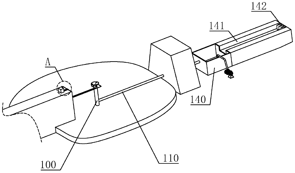
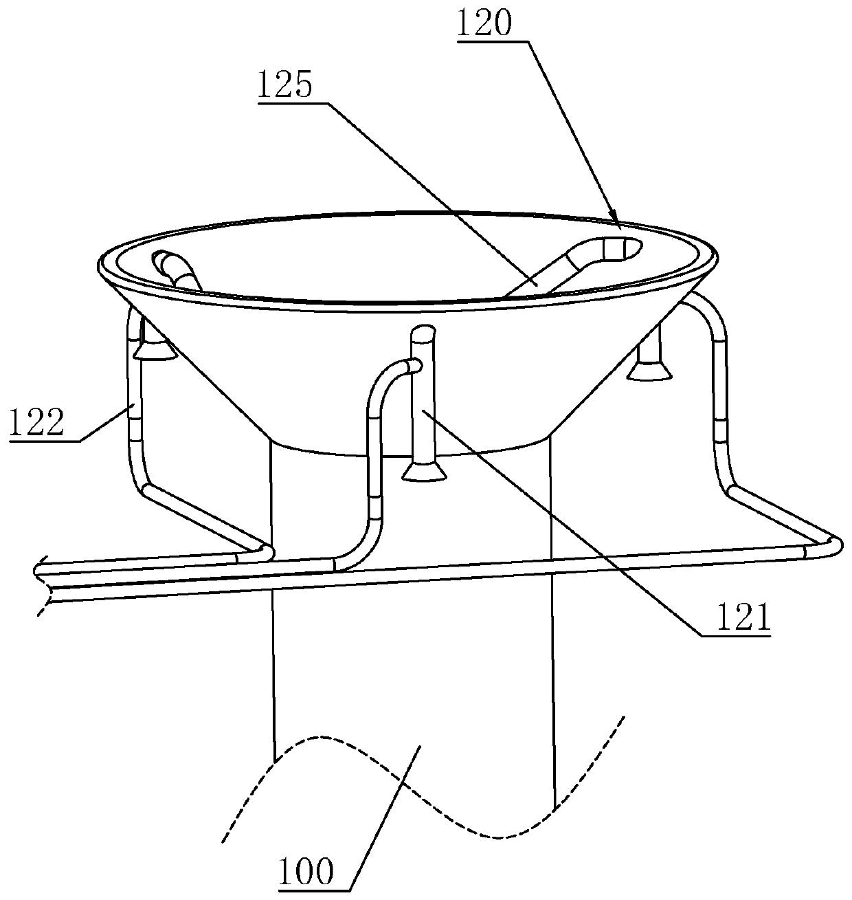
[0045] A kind of reservoir spillway, refer to figure 1 , figure 2 , including a shaft 100 and a water outlet channel 110 vertically connected to one end of the shaft 100. The upper end of the shaft 100 is trumpet-shaped, and a number of siphon pipes 120 are evenly spaced along the circumferential direction at the upper end of the shaft 100. In this embodiment, three siphon pipes 120 are provided. . The siphon pipe 120 is formed by pouring concrete, it passes through the upper side wall of the shaft 100 , one end is located in the shaft 100 , and the other end is located on the outer wall of the shaft 100 .

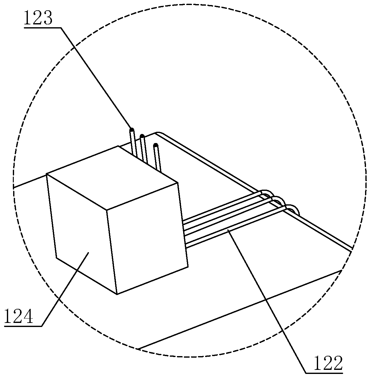
[0046] refer to figure 2 , image 3 , one end of the siphon pipe 120 is arranged on the outer wall of the vertical shaft 100 and is a drainage section 121, and the opening of the drainage section 121 is flared. The end surface of the drainage secti...


PUM


Abstract

The invention relates to the technical field of spillways, in particular to a reservoir spillway and a flood discharge method. The reservoir spillway mainly comprises a vertical shaft and a water outlet channel vertically connected to one end of the vertical shaft. A plurality of siphon pipelines are arranged at the upper end of the vertical shaft in the circumferential direction. One end of eachsiphon pipeline is arranged on the outer wall of the vertical shaft and is a drainage section. The end face of each drainage section is lower than the upper end face of the vertical shaft. The other end of each siphon pipeline is a discharge section. The discharge sections are arranged on the inner wall of the vertical shaft and spirally distributed downwards towards the bottom of the vertical shaft in the circumferential direction. The reservoir spillway and the flood discharge method have the advantages that flood falling into the vertical shaft can fall spirally through the spirally distributed discharge sections, energy is gradually dissipated when the flood moves, impact of the flood on the shaft bottom is reduced, and therefore the probability of damage to the vertical shaft is reduced.

Description

technical field [0001] The invention relates to the technical field of spillways, in particular to a reservoir spillway and a flood discharge method. Background technique [0002] The spillway is the flood control equipment for water conservancy structures such as reservoirs. It is mostly built on one side of the dam, like a large tank. When the water level in the reservoir exceeds the safe limit, the water will flow downstream from the spillway to prevent the dam from being destroyed. Affected by various factors such as geological conditions and surrounding environment, the spillway of small and medium-sized reservoirs used for irrigation and power generation is often designed as a shaft-type spillway. After the water level rises and submerges the shaft, the flood will fall into the shaft and then be discharged. [0003] The Chinese invention patent with the authorized notification number CN103469772B discloses a reservoir shaft type spillway. The spillway includes a shaft ...

Claims


Application Information

Patent Timeline
IPC IPC(8): E02B8/06
CPCE02B8/06
Inventor 覃辉煌吴翠萍薛忠强邱玲
Owner 深圳市东深工程有限公司
Learn More