Humidifying tank and respiratory treatment equipment

A technology of humidification tank and tank body, which is applied in the field of humidification tank and respiratory therapy equipment, which can solve the problem of high probability of water outflow in the humidification tank and achieve the effect of reducing the probability of water outflow

Pending Publication Date: 2020-02-21
VINCENT MEDICAL (DONG GUAN) MFG CO LTD +1
View PDF0 Cites 0 Cited by
  • Summary
  • Abstract
  • Description
  • Claims
  • Application Information

AI Technical Summary

Problems solved by technology

[0004] The disadvantage of the traditional humidification tank is that when the tank body is dumped in the direction of the ventilation channel, the water contained in it is easy to flow out through the ventilation channel. There is a high probability that the water in the tank will flow out

Method used


Image

  • Humidifying tank and respiratory treatment equipment
  • Humidifying tank and respiratory treatment equipment
  • Humidifying tank and respiratory treatment equipment

Examples


Embodiment 1

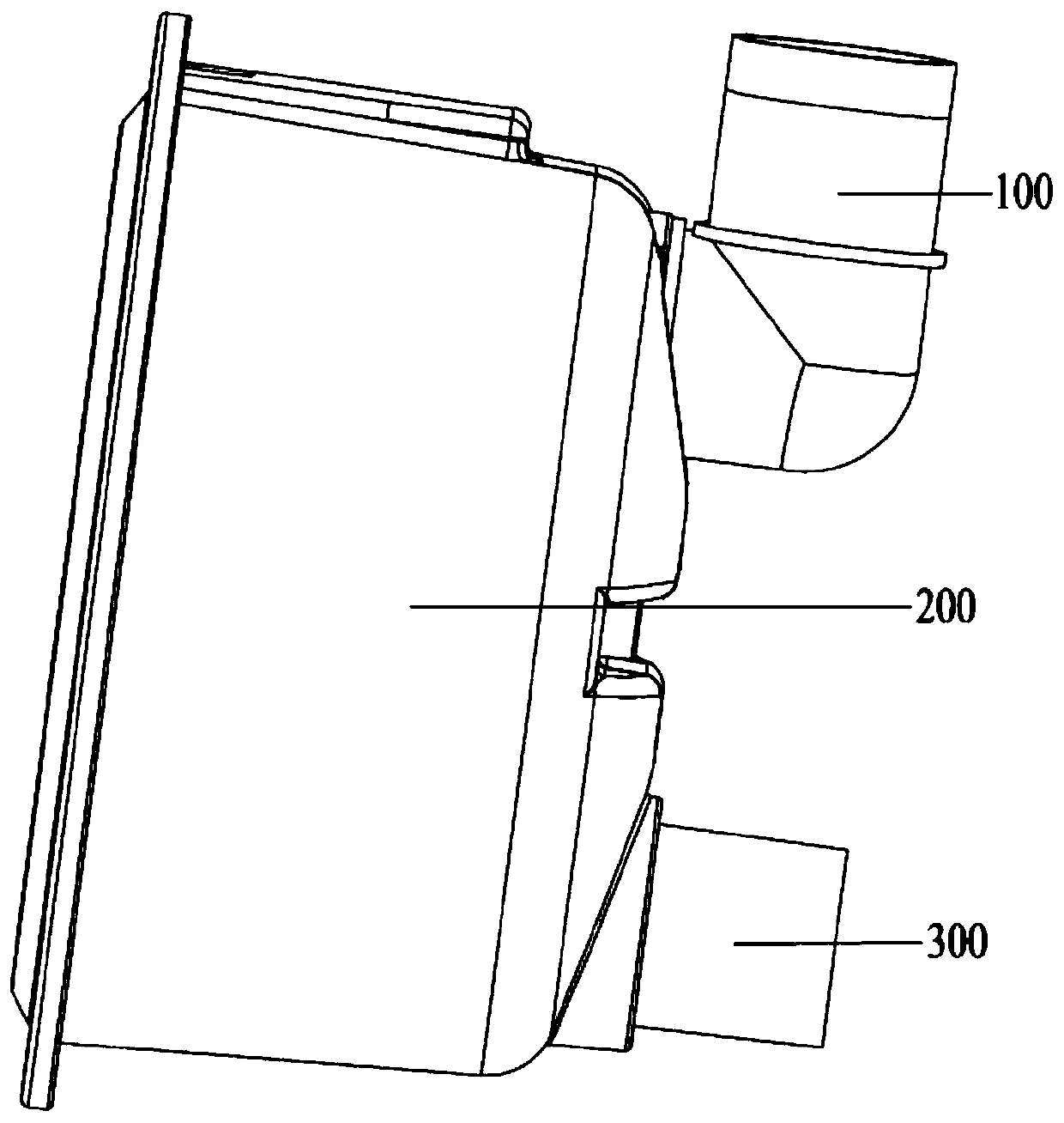
[0045] The first end of the air outlet channel is located inside the tank (including the case where the first end port is opened on the wall of the tank, that is, the case where the outlet pipe 300 extends outward from the wall of the tank is also included).

[0046]The difference between the present invention and the traditional humidification tank is that the first end of the outlet flow channel extends to both sides with a first anti-side flow channel and a second anti-side flow channel, or only extends with the first anti-side flow channel , or only the second anti-sideflow channel is extended. Moreover, when the humidification tank is in an overturned state with the outlet channel lower, the opening heights of the first anti-side flow passage and the second anti-side flow passage are not lower than the water level in the tank. like figure 1 As shown, the dumping state at the lower side of the air outlet channel means that the humidification tank is in an inclined state w...

Embodiment 2

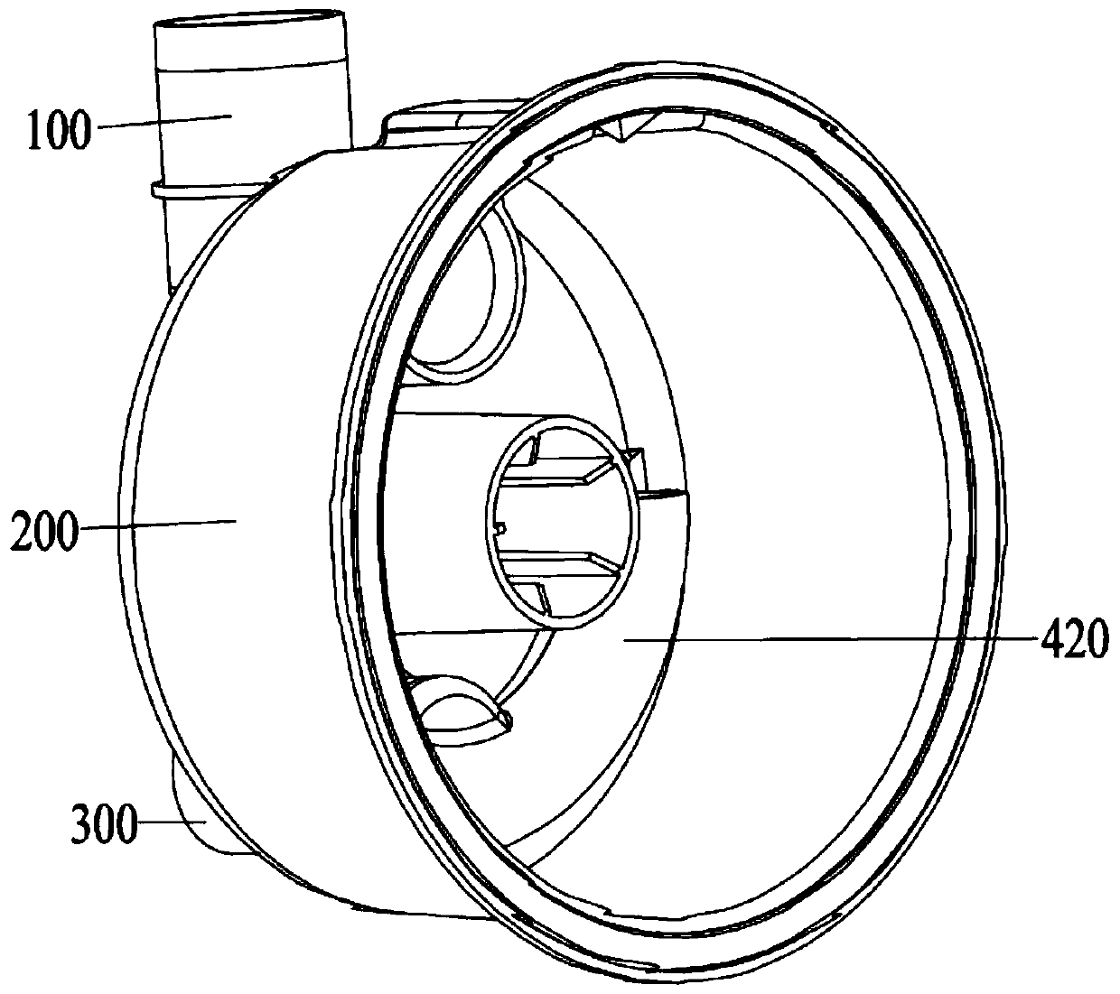
[0063] The second end of the air intake channel is located inside the tank, and the second end extends to both sides with a third anti-side flow channel 430 and a fourth anti-side flow channel 440, when the humidification tank is in the intake air flow When the tank is in the dumping state, the opening heights of the third anti-sideflow passage and the fourth anti-sideflow passage are not lower than the water level in the tank.

[0064] In this embodiment, the third anti-side flow channel and the fourth anti-side flow channel can adopt the same structural configuration as the first anti-side flow channel and the second anti-side flow channel, and can also be made on the basis of retaining the same basic configuration. Adaptive adjustment. The present invention is preferably the latter, and the following will focus on the differences from Embodiment 1, and the similarities will not be repeated; it should be understood that, in addition to the content described below, in this em...

Embodiment 3

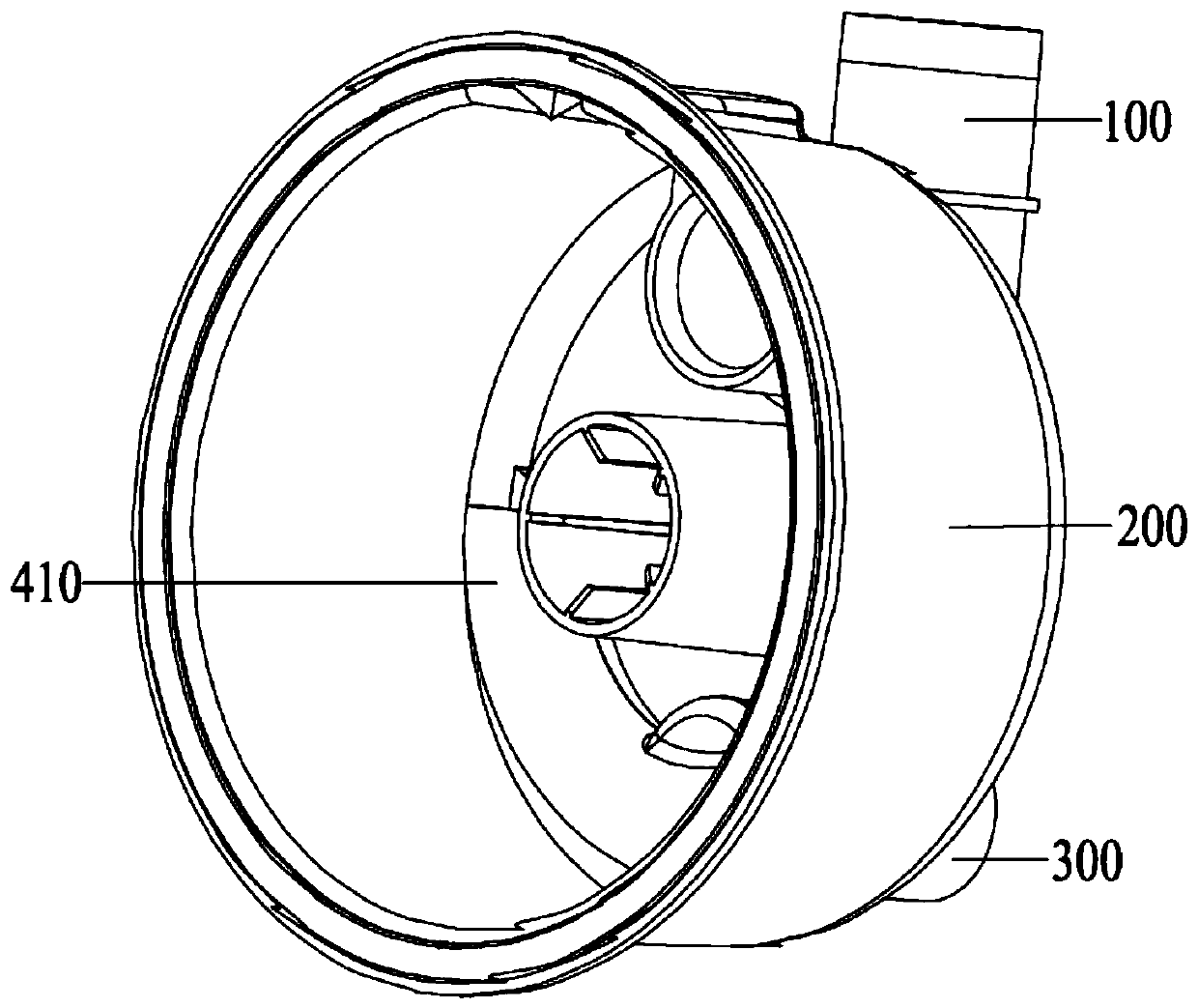
[0071] In this embodiment, the first end of the outlet flow channel and the second end of the inlet flow channel are located inside the tank, and the first end of the outlet flow channel extends to both sides with first The anti-side flow channel and the second anti-side flow channel, when the humidification tank is in the pouring state with the outlet air channel lower, the opening height of the first anti-side flow channel and the second anti-side flow channel is not lower than that of the tank water level in the body. The second end of the air intake channel extends to both sides with a third anti-side flow channel and a fourth anti-side flow channel. And the opening height of the fourth anti-sideflow channel is not lower than the water level in the tank.

[0072] That is to say, embodiment three can have all the features and effects of embodiment one and embodiment two, and its preferred structure is as follows Figure 13 and Figure 14 shown. Figure 13It is a schemat...


PUM


Abstract

The invention discloses a humidifying tank and respiratory therapy equipment. The humidifying tank comprises an air inlet flow channel, a tank body and an air outlet flow channel, the first end of theair outlet flow channel extends towards the side edge to form a lateral flow preventing channel, and / or the second end of the air inlet flow channel extends towards the side edge to form a lateral flow preventing channel; and when the humidifying tank is in a toppling state that the air outlet flow channel is close to the lower part, and / or when the humidifying tank is in a toppling state that the air inlet flow channel is close to the lower part, the opening height of the lateral flow preventing channel is not lower than the water level in the tank body. According to the humidifying tank provided by the invention, when only the air inlet flow channel communicates with the lateral flow preventing channel, water can flow out only when the humidifying tank topples over towards the air outlet flow channel; when only the air outlet flow channel communicates with the lateral flow preventing channel, water can flow out only when the humidifying tank topples over towards the air inlet flow channel; when both the air inlet flow channel and the air outlet flow channel communicate with the lateral flow preventing channel, no matter whether the humidifying tank topples over towards the air inlet flow channel or the air outlet flow channel, no water flows out. The scheme reduces the probability of water outflow.

Description

technical field [0001] The invention relates to the technical field of medical equipment, in particular to a humidification tank and respiratory treatment equipment. Background technique [0002] The ventilator humidification tank is an instrument used in conjunction with the ventilator (or other respiratory therapy equipment with the same function), which stores moisture inside, and is usually connected between the ventilator and the gas delivery tube to decontaminate the passing gas. Humidification; if the humidification tank is heated, the passing gas can also be heated. [0003] A traditional humidification tank usually includes: a tank body, the tank body is provided with an inlet flow channel and an outlet flow channel (collectively referred to as a ventilation channel), the inlet flow channel is connected to the ventilator, and the outlet flow channel is connected to the gas delivery pipe, and the tank body is used for Hold water. [0004] The disadvantage of the tr...

Claims


Application Information

Patent Timeline
Patent Type & Authority Applications(China)
IPC IPC(8): A61M16/16A61M16/00A61M16/10
CPCA61M16/0003A61M16/109A61M16/162
Inventor 胡振湘徐结兵于海滨
Owner VINCENT MEDICAL (DONG GUAN) MFG CO LTD
Why Eureka
Try Eureka