Anti-scouring concrete repairing device

A concrete and anti-abrasion technology, applied in clay preparation devices, unloading devices, cement mixing devices, etc., can solve the problems of deep cracks that are difficult to fill, leakage of slurry, low efficiency, etc., to improve the effect of slurry replenishment, The effect of solving slurry leakage and reducing the amount of stirring

Active Publication Date: 2018-12-18
GUANGDONG NO 2 HYDROPOWER ENGINEERING COMPANY LTD
View PDF10 Cites 13 Cited by
  • Summary
  • Abstract
  • Description
  • Claims
  • Application Information

AI Technical Summary

Problems solved by technology

The crack defect reinforcement of the prior art has the following deficiencies: First, for cracks in the vertical direction or cracks on the inclined surface, the problem of grout leakage is likely to occur when using the traditional grouting method; When the concrete slurry is injected into the crack in the direction of gravity, the slurry will flow down under the action of gravity, and it is difficult to fill the depth of the crack, resulting in low reinforcement efficiency; second, when the crack is long, only through the concrete itself Leveling, it is difficult to ensure that it can fill the entire crack. At this time, it is necessary to move the position of the grouting pipe to realize the filling of the crack. In the existing technology, the grouting is often completed by manually moving the grouting pipe Third, after the crack is reinforced, there will be a large repair mark between the reinforced area and the non-reinforced area. From the surface, the reinforced area will bulge a little compared to the non-reinforced area, which is Because the reinforced concrete is naturally solidified in the cracks, its surface smoothness is poor; Fourth, when actually reinforcing, it is usually necessary to install a bracket to fix the position of the grouting pipe, because it is for repairing vertical cracks or oblique Cracks on the drape; in the prior art, the grouting pipe is usually fastened by riveting or manual holding. Although the riveting method has a better fastening effect and saves labor, this method is to destroy the wall or plate. achieved at the expense of the body

Method used


Image

  • Anti-scouring concrete repairing device
  • Anti-scouring concrete repairing device
  • Anti-scouring concrete repairing device

Examples


Embodiment 1

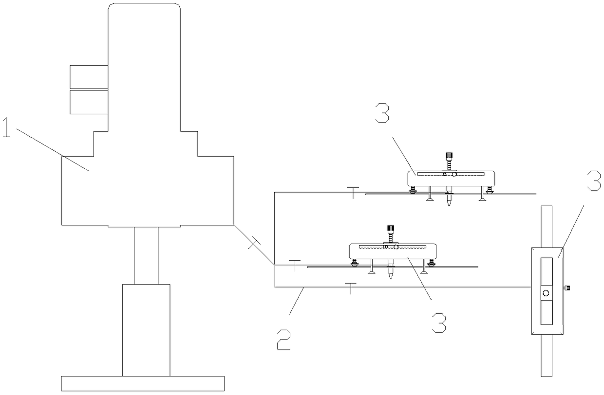
[0058] Such as figure 1 As shown, the present invention discloses an anti-scouring concrete repair device, which includes a mixing device 1 and a grouting machine 3. The mixing device 1 is used to stir the concrete slurry, and the concrete slurry is injected through the grouting machine 3. into concrete cracks. The mixing and stirring device 1 can work in a cycle according to the order of batching first and then discharging, and multiple pipelines 2 are communicated between the mixing and stirring device 1 and the slurry replenishing machine 3 .

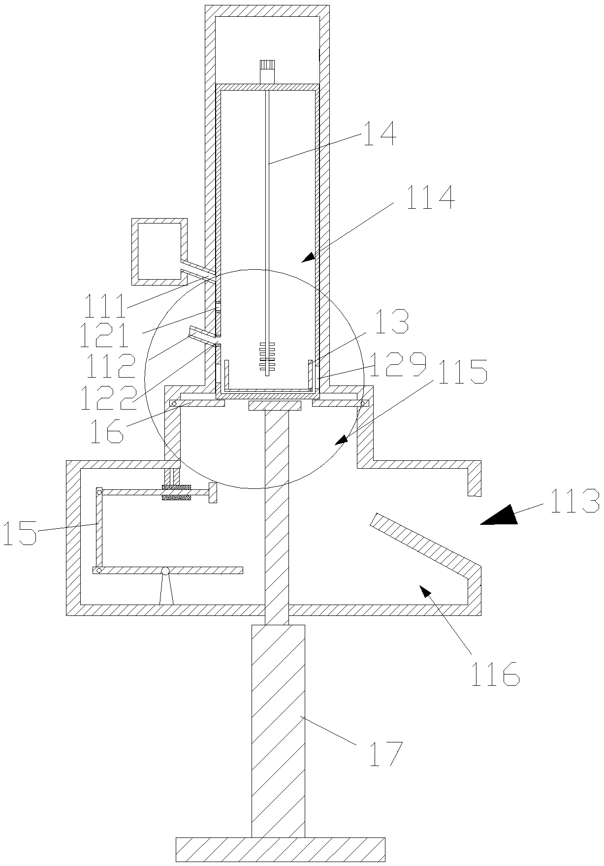
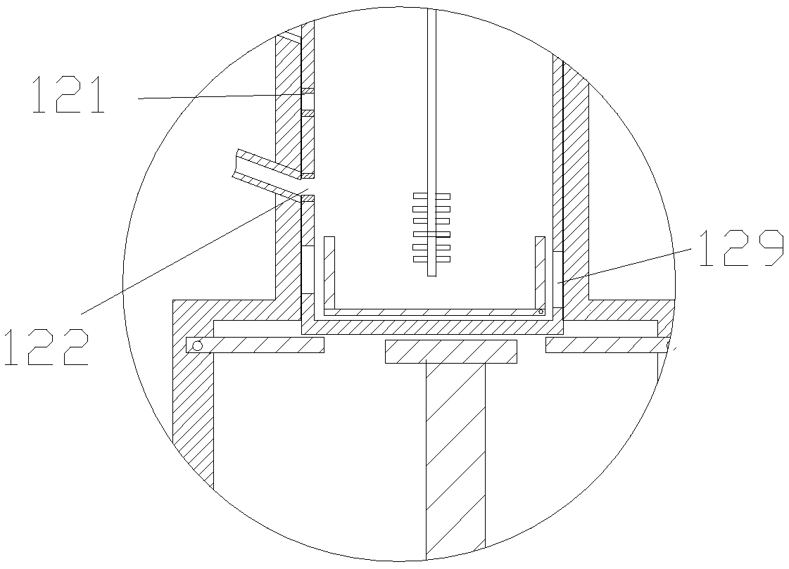
[0059] Such as Figure 2-4 As shown, the mixing and stirring device 1 includes a housing 11 , a built-in frame 12 , a mixing bin 13 , a stirring member 14 , a lever-type driving pusher assembly 15 , a baffle assembly 16 , and an elastic support member 17 .

[0060]The casing 11 is separated from top to bottom with a feed inlet 111, a water inlet 112, and a discharge outlet 113. The inner cavity of the casing 11 includes a passage c...

Embodiment 2

[0078] Such as Figure 2-4 As shown, the difference of this embodiment compared with the above-mentioned embodiments is that the baffle plate assembly 16 includes a first baffle plate 161 and a second baffle plate 162 which are mirror-symmetrical, the hinged end of the first baffle plate 161, and the hinged end of the second baffle plate 162 The hinge ends are respectively hinged on both sides of the baffle installation cavity 115 . The length of the gap between the free end of the first baffle 161 and the free end of the second baffle 162 in a natural state is shorter than the length of the bottom of the housing 11 . The hinged end of each baffle is hinged to the inner wall of the baffle installation cavity 115 via a second torsion spring (not shown in the figure). The second torsion spring is assembled to the free end of the baffle in a horizontal state. When the free end of the baffle is in a horizontal state, the hinged end of the baffle can be attracted to the inner wal...

Embodiment 3

[0082] Such as Figure 8 As shown, the difference between the present embodiment and the above-mentioned embodiment is that the lever-type transmission pusher assembly 15 includes a lever 151, a transmission rod 152, a sleeve 153, and a push rod 154, and one end of the lever 151 is hinged to the lower end of the transmission rod 152, The upper end of the transmission rod 152 is hinged with one end of the push rod 154 , and the other end of the push rod 154 passes through the sleeve 153 so as to be in contact with or connected to the sliding push plate 133 . The other end of the lever 151 can be in contact with the bottom of the housing 11 .

[0083]When housing 11 descends to its contact with the other end of lever 151, the other end of lever 151 descends, and one end of lever 151 rotates upwards, drives drive rod 152 to rotate, and drives push rod 154 to push sliding push plate 133.


PUM


Abstract

The invention discloses an anti-scouring concrete repairing device. The anti-scouring concrete repairing device comprises a mixing and stirring device and a slurry supplement pipe. The mixing and stirring device is used for stirring concrete slurry, and the concrete slurry is injected into concrete cracks through the slurry supplement pipe. The anti-scouring concrete repairing device is characterized in that the mixing and stirring device can cyclically work to prepare materials first and then to discharge the materials, and a plurality of pipelines arranged between the mixing and stirring device and the slurry supplement pipe. The anti-scouring concrete repairing device has the advantages that the cracks are fully filled, the probability of slurry leakage is lowered, the surface flatnessis high after reinforcement, and a grouting pipe can slide in the cracks to achieve slurry supplement; the mounting stability of a support is high, and a wall is not likely to be damaged, or the adhesion strength of a plate body is high; intermittent material supplement and quantitative stirring are conducted, so that raw material waste is reduced, the cracks are fully filled, the probability of slurry leakage is lowered, the surface flatness is high after reinforcement, the grouting pipe can slide in the cracks to achieve slurry supplementation; and the mounting stability of the support is high, and the wall is not likely to be damaged, or the adhesion strength of the plate body is high.

Description

technical field [0001] The invention relates to the technical field of concrete reinforcement, in particular to an abrasion-resistant concrete repair device. Background technique [0002] Concrete pouring refers to the process of pouring concrete into the mold until it is plasticized. In civil engineering, concrete and other materials are put into the mold to make a predetermined shape. Usually, concrete defects include the following situations. First, the interior of the concrete has voids and voids, which are commonly known as "two skins"; The surface of the concrete is not cleaned properly, and the concrete surface is stuck when the formwork is removed; or, the formwork release agent is not evenly applied, and some parts are missing or invalid, and the concrete surface and the formwork are bonded to cause pockmarks; third, cracks and cracks appear on the concrete surface The problem. The general mechanism of cracks is generally believed to be due to the fact that the in...

Claims


Application Information

Patent Timeline
Patent Type & Authority Applications(China)
IPC IPC(8): B28C5/16B28C5/08B28C7/16E04G23/02
CPCB28C5/0856B28C5/166B28C7/16E04G23/0211
Inventor 谢祥明乔晓锋赵雅玲姚楚康邱晓艳
Owner GUANGDONG NO 2 HYDROPOWER ENGINEERING COMPANY LTD
Why Eureka
Try Eureka