Mixing stirring device for scouring and abrading resisting concrete for hydraulic engineering

A water conservancy project, mixing and stirring technology, applied in the direction of cement mixing equipment, clay preparation equipment, chemical instruments and methods, etc., can solve the problems of a large amount of waste, high power consumption, etc., to reduce waste, reduce the amount of mixing, control a single mixing volume effect

Active Publication Date: 2018-11-30
GUANGDONG NO 2 HYDROPOWER ENGINEERING COMPANY LTD
View PDF7 Cites 2 Cited by
  • Summary
  • Abstract
  • Description
  • Claims
  • Application Information

AI Technical Summary

Problems solved by technology

As we all know, the pouring and repairing of concrete is based on the concrete mixing. In actual pouring, in order to meet the fluidity of the concrete and prevent it from solidifying, the mixing device needs to be running all the time to mix the mixed concrete materials, which requires a lot of energy consumption. Large power; In addition, when repairing, this method of mixing first and then repairing will generate a lot of waste

Method used


Image

  • Mixing stirring device for scouring and abrading resisting concrete for hydraulic engineering
  • Mixing stirring device for scouring and abrading resisting concrete for hydraulic engineering
  • Mixing stirring device for scouring and abrading resisting concrete for hydraulic engineering

Examples


Embodiment 1

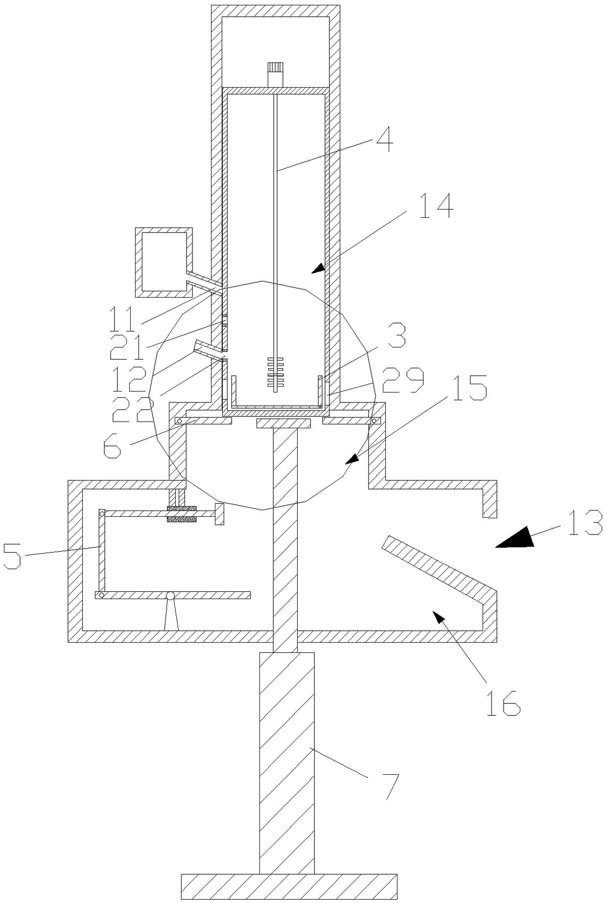
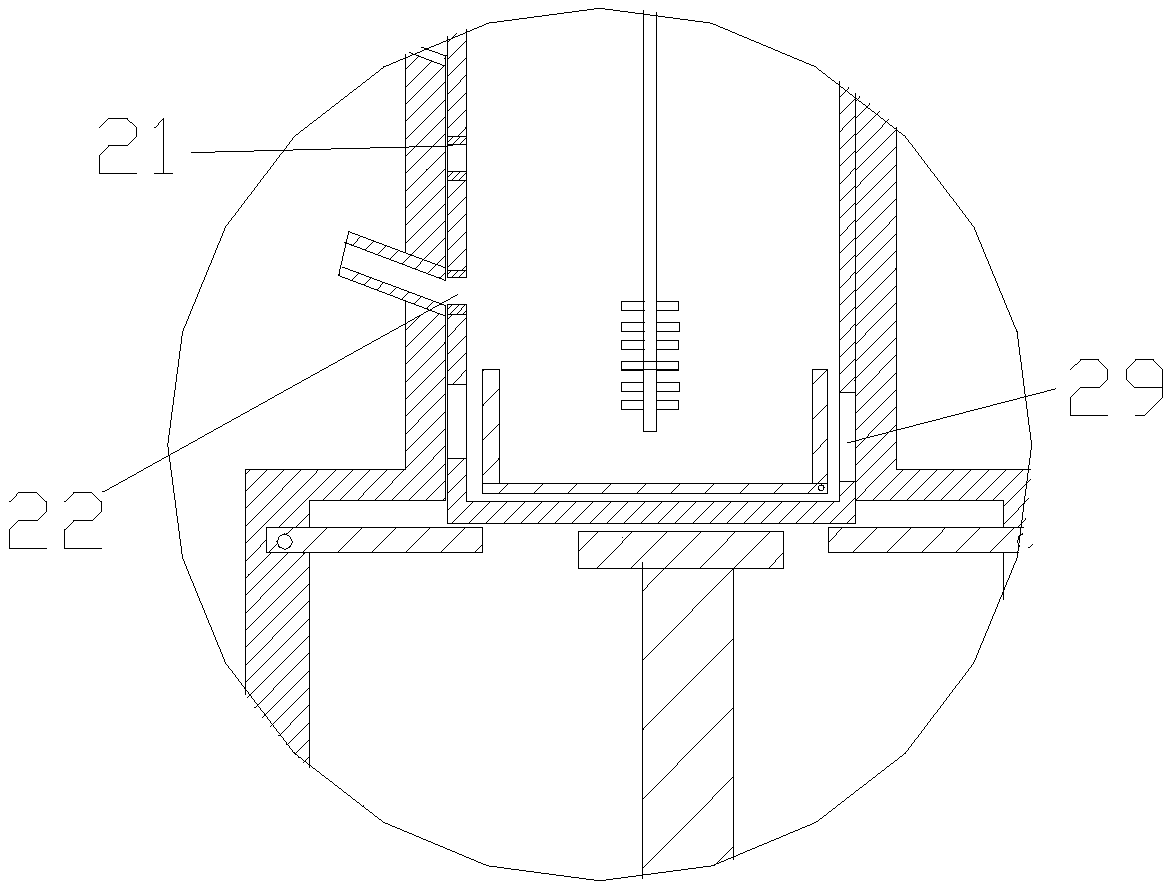
[0042] Such as Figure 1-3 As shown, this embodiment discloses a mixing and stirring device for the production of anti-scouring concrete for water conservancy projects, including a housing 1, a built-in frame body 2, a mixing chamber 3, a stirring member 4, a lever-type transmission pusher assembly 5, and a baffle Component 6, elastic support 7.

[0043] The housing 1 is separated from top to bottom with a feed inlet 11, a water inlet 12, and a discharge outlet 13. The inner cavity of the housing 1 includes a passage cavity 14 and a baffle installation cavity 15 that are connected to each other from top to bottom. , Bottom chamber 16. The cross-sections of the channel cavity 14, the baffle mounting cavity 15, and the bottom cavity 16 increase sequentially. Both the feeding port 11 and the water inlet port 12 communicate with the channel cavity 14 . The built-in frame body 2 is built in the inner cavity of the housing 1, wherein, the outer surface of the built-in frame body ...

Embodiment 2

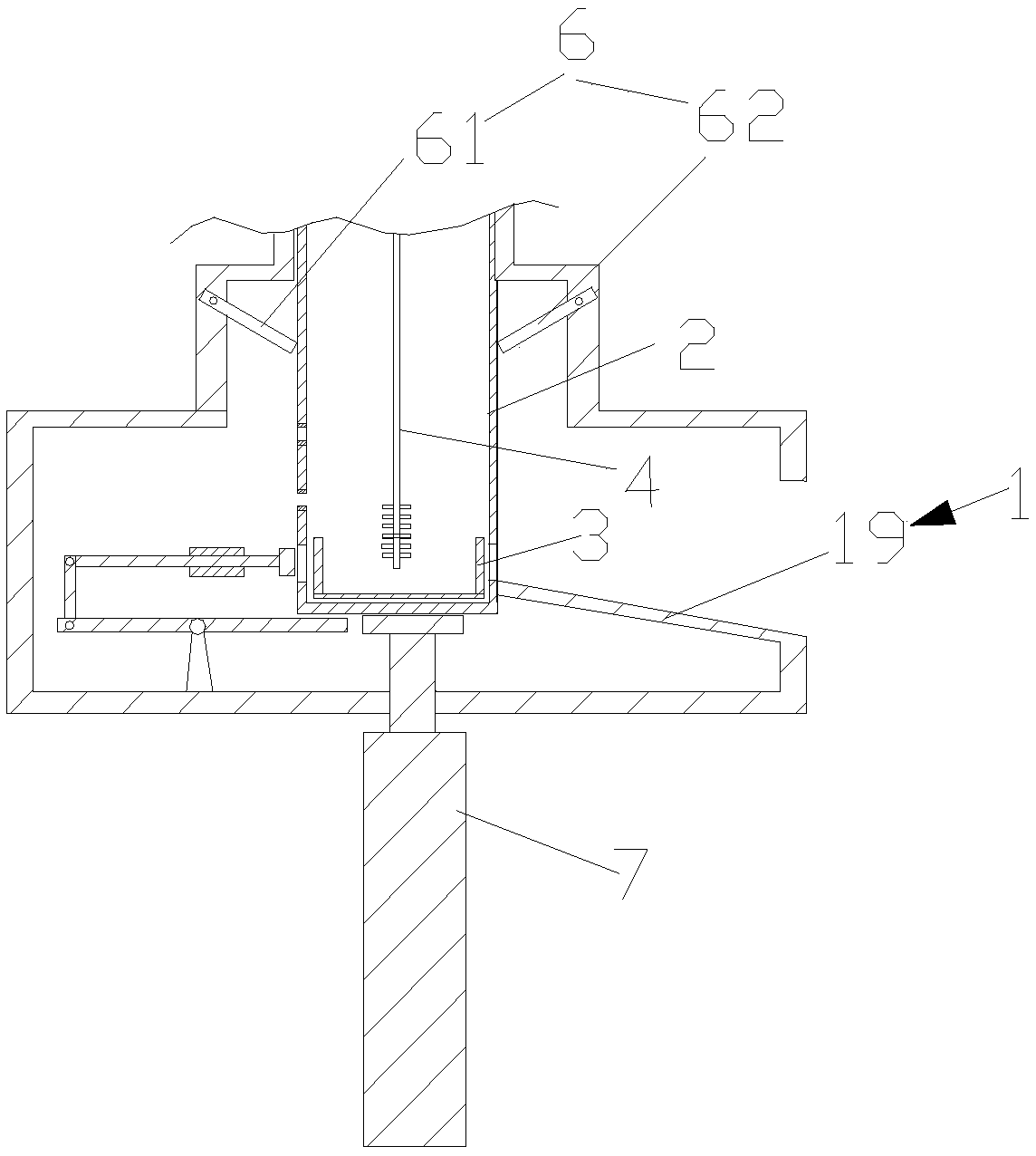
[0054] Such as Figure 1-3 As shown, the difference between this embodiment and the above-mentioned embodiments is that the baffle plate assembly 6 includes a mirror-symmetrical first baffle plate 61 and a second baffle plate 62, the hinged end of the first baffle plate 61, and the hinged end of the second baffle plate 62. The hinge ends are respectively hinged on both sides of the baffle installation cavity 15 . The length of the gap between the free end of the first baffle 61 and the free end of the second baffle 62 in a natural state is shorter than the length of the bottom of the housing 1 . The hinged end of each baffle is hinged to the inner sidewall of the baffle installation cavity 15 through a second torsion spring (not shown in the figure). The second torsion spring is assembled to the free end of the baffle in a horizontal state. When the free end of the baffle is in a horizontal state, the hinged end of the baffle can be attracted to the inner sidewall of the baf...

Embodiment 3

[0058] Such as Figure 5-6 As shown, the difference of the present embodiment compared with the foregoing embodiments is that the lever-type transmission pusher assembly 5 includes a lever 51, a transmission rod 52, a sleeve 53, and a push rod 54, and one end of the lever 51 is hinged with the lower end of the transmission rod 52, The upper end of the transmission rod 52 is hinged with one end of the push rod 54 , and the other end of the push rod 54 passes through the sleeve 53 so as to be in contact with or connected to the sliding push plate 33 . The other end of the lever 51 can be in contact with the bottom of the housing 1 .

[0059] When housing 1 descends to its contact with the other end of lever 51, the other end of lever 51 descends, and one end of lever 51 rotates upwards, drives transmission rod 52 to rotate, and drives push rod 54 to push sliding push plate 33.


PUM


Abstract

The invention discloses a mixing stirring device for scouring and abrading resisting concrete for hydraulic engineering. The mixing stirring device comprises a shell, an inner frame, a stirring bin, astirring piece, a lever type transmission pushing assembly, a baffle assembly and an elastic supporting piece. The baffle assembly is hinged to the inner side wall of a baffle installing cavity and used for supporting the shell. The baffle assembly can rotate along with downward movement of the shell. When the baffle assembly supports the shell, a water feeding port communicates with a water inlet. The stirring piece is arranged in an inner cavity of the shell and used for stirring materials in the stirring bin. The shell moves downwards and can drive a lever in the lever type transmission pushing assembly to rotate, and a pushing rod in the lever type transmission pushing assembly is made to push a sliding push plate in the end plate position direction through transmission. The elastic supporting piece is used for supporting the bottom of the shell, does the contraction movement along with descending of the shell and does the stretching movement along with ascending of the shell. Themixing stirring device has the beneficial effects of intermittent material supplementing, volume dividing stirring and raw material waste reducing.

Description

technical field [0001] The invention relates to the technical field of concrete construction, in particular to a mixing and stirring device for producing anti-scouring concrete used in water conservancy projects. Background technique [0002] Concrete mixing is an operation method in which cement, lime, water and other materials are mixed and then stirred evenly. There are two types of concrete mixing: manual mixing and mechanical mixing of water. Among them, mechanical stirring means adding stones, cement and sand to the mixer in turn, dry mixing evenly, and then adding water, mixing evenly. [0003] Stirring devices in the prior art, such as the concrete mixer disclosed in patent application 2015107305359, introduce a liquid rejection box into the traditional stirring device, and realize the uniformity of material mixing and stirring through the centrifugal action of the liquid rejection box. Another example is a new type of concrete mixer disclosed in patent application...

Claims


Application Information

Patent Timeline
IPC IPC(8): B28C5/08
CPCB28C5/08
Inventor 谢祥明乔晓锋赵雅玲姚楚康邱晓艳
Owner GUANGDONG NO 2 HYDROPOWER ENGINEERING COMPANY LTD
Why Eureka
Try Eureka