Chain tensioner and relief valve unit

A chain tensioning device and tensioning device technology, applied in safety valves, valve devices, transmission devices, etc., can solve problems such as noise, vibration, and timing chain damage, and achieve the effect of suppressing vibration and reducing assembly hours

Active Publication Date: 2016-10-26
TSUBAKIMOTO CHAIN CO
View PDF11 Cites 12 Cited by
  • Summary
  • Abstract
  • Description
  • Claims
  • Application Information

AI Technical Summary

Problems solved by technology

[0010] In such a chain tensioner, when an excessive tensile force is generated on the timing chain during use, the pressure in the oil pressure chamber becomes excessive, and noise, vibration, or damage to the timing chain may occur.

Method used


Image

  • Chain tensioner and relief valve unit
  • Chain tensioner and relief valve unit
  • Chain tensioner and relief valve unit

Examples


Embodiment 1

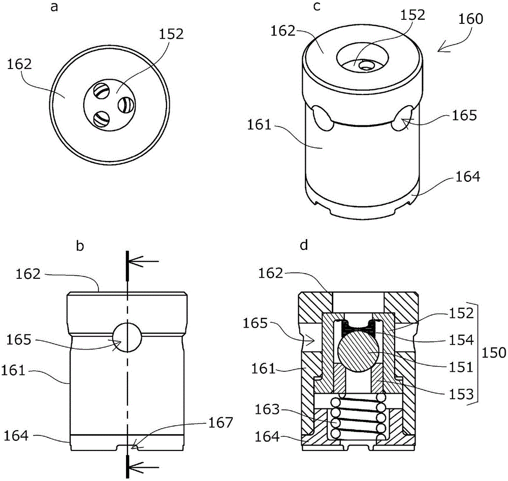
[0055] The chain tensioner 100 and the safety valve unit 160 according to the first embodiment of the present invention will be described with reference to the drawings.

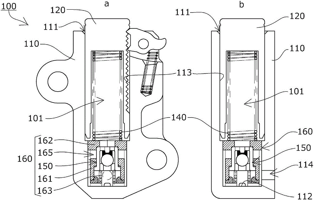
[0056] Such as figure 1 As shown, the chain tensioner 100 according to the first embodiment of the present invention includes: a tensioner body 110 having a cylindrical plunger receiving hole 111 with one side open; and a cylindrical plunger 120 slidably and the coil spring 140, which is the biasing mechanism, is freely accommodated in the pressure oil chamber 101 formed between the plunger receiving hole 111 and the plunger 120 and faces the plunger in the protruding direction. 120 applied force.

[0057] A relief valve unit 160 is provided at the bottom 112 of the plunger housing hole 111 of the tensioner main body 110 , and an oil supply hole 114 is provided near the bottom 112 .

[0058] Furthermore, the chain tensioner 100 according to this embodiment is a so-called ratchet type tensioner, in which a...

Embodiment 2

[0080]A chain tensioner 200 and a safety valve unit 260 according to a second embodiment of the present invention will be described with reference to the drawings.

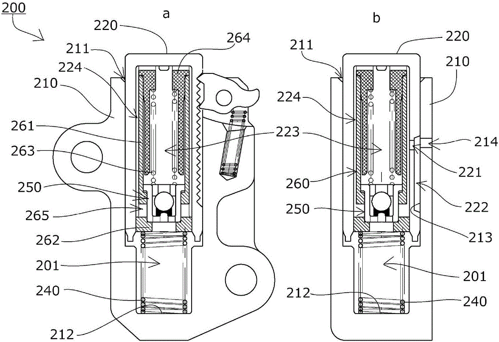
[0081] Such as image 3 As shown, the chain tensioner 200 is as follows, the plunger 220 internally has an oil storage chamber 223 communicating from the oil supply hole 214 through the supply path 222 and the plunger supply hole 221, and the safety valve unit 260 is arranged in the oil storage chamber 223. , Between the outer periphery of the safety valve sleeve 261 and the inner surface of the plunger 220, an oil flow path 224 through which the released oil returns to the oil storage chamber 223 is formed.

[0082] Such as Figure 4 As shown, the safety valve unit 260 is formed to extend over the entire oil storage chamber 223 , and the configuration other than the length is the same as that of the safety valve unit 160 according to the first embodiment (the hundreds digit of the symbol is 2).

[0083] The saf...

Embodiment 3

[0097] A chain tensioner 300 according to a third embodiment of the present invention will be described with reference to the drawings.

[0098] Such as Figure 6 As shown, like the first embodiment, the chain tensioner 300 according to the third embodiment of the present invention includes: a tensioner main body 310 having a cylindrical plunger receiving hole 311 with one side open; A plunger 320 is slidably inserted into the plunger receiving hole 311; A force is applied to the plunger 320 in the protruding direction.

[0099] In the plunger receiving hole 311 of the tensioner main body 310, with Figure 4 The same safety valve unit 260 shown in the second embodiment is slidably inserted into the plunger 320 from the bottom 312 with the side of the safety valve seat 262 facing the protruding direction of the plunger 320 , and an oil supply valve is provided near the bottom 312 . Hole 314.

[0100] Thus, the pressure oil chamber 301 is formed on the protruding side inside...


PUM


Abstract

To provide a chain tensioner and a relief valve unit that enable a reduction in the number of parts to be machined and the number of assembling steps, reduce the amount of oil flowing out to the outside, and prevent damage on a check valve, without having to increase the size of the chain tensioner. The chain tensioner includes a check valve unit(150) that suppresses reverse flow of oil flowing into an oil pressure chamber(101), and a relief valve unit(160) that releases the oil when the pressure inside the oil pressure chamber(101) reaches or exceeds a predetermined high pressure. The check valve unit(150) is disposed as a valve element of the relief valve unit(160), and the relief valve unit and the check valve unit are formed integral with each other.

Description

technical field [0001] The present invention relates to a chain tensioner for properly maintaining the tension of the chain. a plunger receiving hole; and a urging mechanism that is retractably accommodated in a pressure oil chamber formed between the plunger receiving hole and the plunger, and applies force to the plunger in a protruding direction. Background technique [0002] Conventionally, a chain tensioner that appropriately maintains the tension of the chain is generally used. For example, the following technology is known in which a crankshaft and a camshaft sprocket respectively disposed in an engine room are connected without joints by moving a guide block. In the structure of the chain guide in which a transmission chain such as a rotating roller chain is used for sliding guidance, a chain tensioner is used to apply force to the swing chain guide with a moving guide block in order to maintain the tension properly. [0003] For example, if Figure 8 As shown, the ...

Claims


Application Information

Patent Timeline
Patent Type & Authority Applications(China)
IPC IPC(8): F16H7/08F16K17/164F16K17/04F16K15/04
CPCF16H7/0848F16K15/044F16K17/04F16K17/164F16H2007/0814F16H2007/0806F16H2007/0853F16H2007/0859F16H7/0836F16H2007/0812F16H2007/0893F16K17/18F16K15/04F16H7/06F16K17/0406F16K27/02F16K17/02
Inventor 国松幸平榑松勇二
Owner TSUBAKIMOTO CHAIN CO
Why Eureka
Try Eureka