Cutting device for metal material machining

A cutting device and metal material technology, applied in metal processing equipment, metal processing machinery parts, positioning devices, etc., can solve the problems of steel fixing, steel is easy to shake, and cutting efficiency is affected

Inactive Publication Date: 2020-02-21
徐州铭博矿山科技有限公司
View PDF6 Cites 0 Cited by
  • Summary
  • Abstract
  • Description
  • Claims
  • Application Information

AI Technical Summary

Problems solved by technology

[0002] Metal materials refer to materials with luster, ductility, easy conduction, heat transfer and other properties. They are generally divided into ferrous metals and non-ferrous metals. Ferrous metals include iron, chromium, manganese, etc. Among them, steel is the basic structural material, called As the "skeleton of industry", due to the advancement of science and technology, the wide application of various new chemical materials and new non-metallic materials, the substitutes for steel continue to increase, and the demand for steel is relatively declining. The dominant position in the composition of raw materials is still difficult to replace. Steel needs to use a lot of equipment in the process of processing, and the cutting device is one of them. The cutting device in the prior art cannot fix the steel in the process of cutting steel. It makes the steel easy to shake when cutting, so that the cutting position of the steel changes, so that the steel cannot be cut as expected, which affects the cutting efficiency

Method used


Image

  • Cutting device for metal material machining
  • Cutting device for metal material machining

Examples


Embodiment Construction

[0016] The following will clearly and completely describe the technical solutions in the embodiments of the present invention with reference to the accompanying drawings in the embodiments of the present invention. Obviously, the described embodiments are only some, not all, embodiments of the present invention. Based on the embodiments of the present invention, all other embodiments obtained by persons of ordinary skill in the art without making creative efforts belong to the protection scope of the present invention.

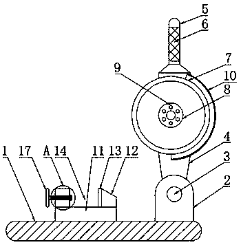
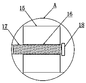
[0017] The present invention provides such Figure 1-2 The cutting device for metal material processing shown includes a base 1, a fixed block 2 is arranged on one side of the top of the base 1, a rotating shaft 3 is arranged inside the fixed block 2, and a movable frame is arranged on the top of the fixed block 2 4. The top of the movable frame 4 is provided with a fixed handle 5, and the outer wall of the fixed handle 5 is provided with a non-slip sleeve 6, ...


PUM


Abstract

The invention discloses a cutting device for metal material machining. The cutting device comprises a base, a fixed block is arranged on one side of the top of the base, a rotating shaft is arranged in the fixed block, a movable rack is arranged on the top of the fixed block, a fixed handle is arranged on the top of the movable rack, the outer wall of the fixed handle is provided with an anti-slide sleeve, a cutting blade is arranged on one side of the movable rack, a fixed gasket is arranged on one side of the cutting blade, a screw is arranged in the fixed gasket, a protection cover is arranged on the outer side of the cutting blade, a cushion block is arranged on the top of the base, and an abutting block is arranged on one side of the top of the cushion block. Through the abutting block, a friction layer, a handle bolt and an abutting plate, during steel cutting, the steel can be fixed, during steel cutting, shaking is avoided, the cutting position of the steel is not changed, thesteel can be cut according to anticipation, and the cutting efficiency cannot be affected.

Description

technical field [0001] The invention relates to the technical field of metal processing, in particular to a cutting device for metal material processing. Background technique [0002] Metal materials refer to materials with luster, ductility, easy conduction, heat transfer and other properties. They are generally divided into ferrous metals and non-ferrous metals. Ferrous metals include iron, chromium, manganese, etc. Among them, steel is the basic structural material, called As the "skeleton of industry", due to the advancement of science and technology, the wide application of various new chemical materials and new non-metallic materials, the substitutes for steel continue to increase, and the demand for steel is relatively declining. The dominant position in the composition of raw materials is still difficult to replace. Steel needs to use a lot of equipment in the process of processing, and the cutting device is one of them. The cutting device in the prior art cannot fix...

Claims


Application Information

Patent Timeline
Patent Type & Authority Applications(China)
IPC IPC(8): B23Q3/06
CPCB23Q3/06
Inventor 吴信亮
Owner 徐州铭博矿山科技有限公司
Why Eureka
Try Eureka