


Quick Research
Generate reliable direction feasibility study reports for your R&D in just a few steps.

Technical Q&A
Discover and master advanced knowledge NOW. Basics, ideas, possibilities, all at once.

Find Solutions
As an expert in R&D theories, this can generate solutions to your technical problems instantly.

Evaluate Feasibility
Analyze your overall solution with one click, know your potential R&D risks in advance.

Monitor Landscape
Get weekly tech updates, stay abreast of the latest tech innovations and key insights.
Clamping jaw structure capable of achieving precise pointer positioning
A precise positioning and gripper technology, applied in the direction of chucks, manipulators, manufacturing tools, etc., can solve the problem of motor shaft bending and other problems, and achieve the effect of not easy to bend, reduce production costs, scrap rate, and high pass rate
- Summary
- Abstract
- Description
- Claims
- Application Information
AI Technical Summary
Problems solved by technology
Method used
Image

Examples
specific Embodiment approach 1
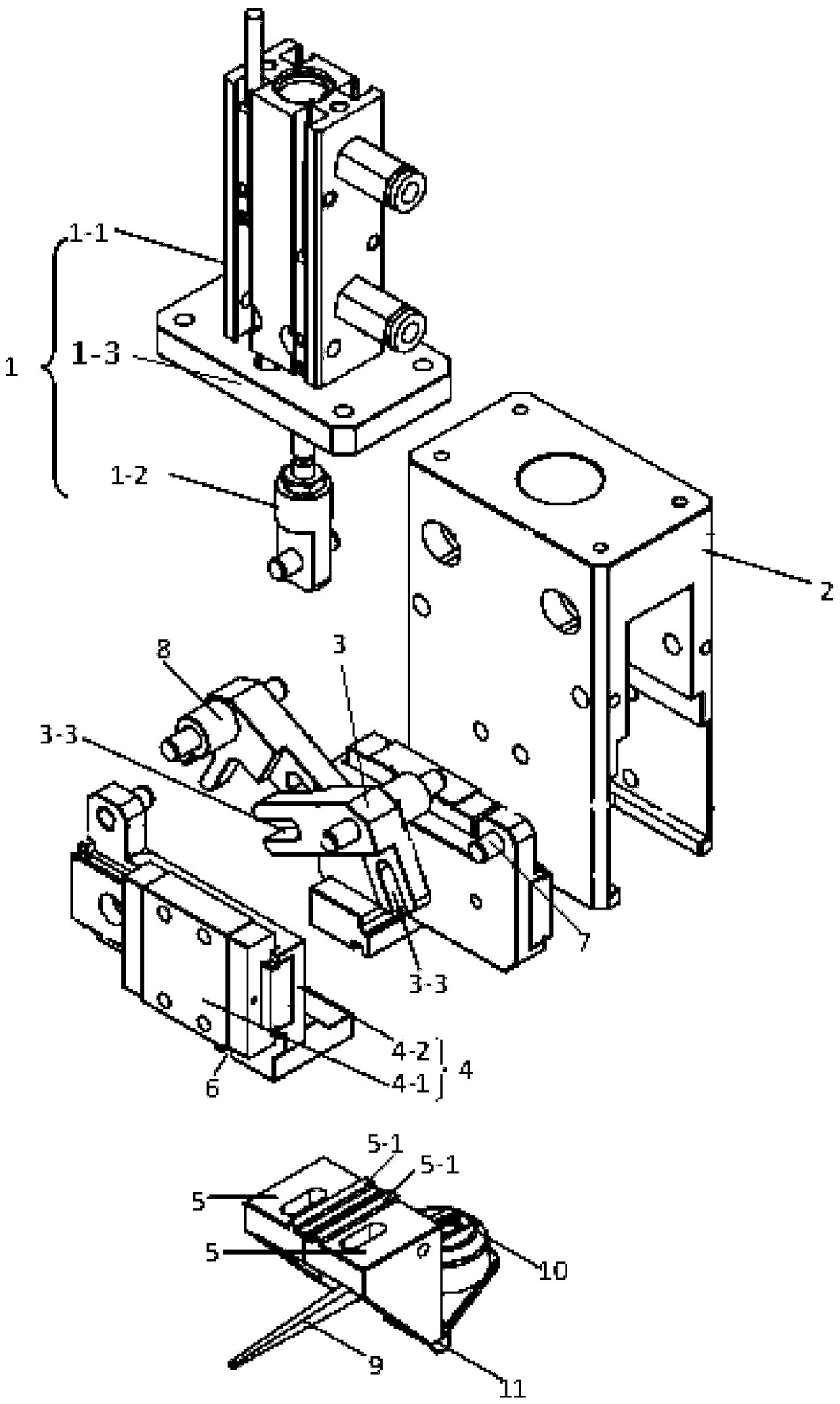
[0029] Specific implementation mode one: refer to Figure 1 to Figure 8 Describe this embodiment in detail. The jaw structure that enables precise positioning of the pointer described in this embodiment includes a jaw cylinder body 2, a jaw cylinder assembly 1, two guide rail assemblies 4, and two jaw connecting rods. 3 and two jaws 5,
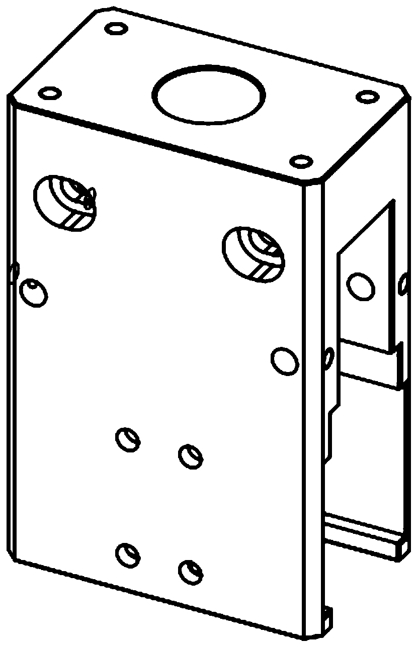
[0030] The jaw cylinder body 2 is a cuboid structure that is hollow inside and has an open bottom end and two opposite side walls.
[0031] The jaw cylinder assembly 1 includes a cylinder 1-1, a cylinder transition rod assembly 1-2 and a jaw cylinder fixing plate 1-3,
[0032] Both guide rail assemblies 4 include a linear guide rail 4-1 and a slide block 4-2,
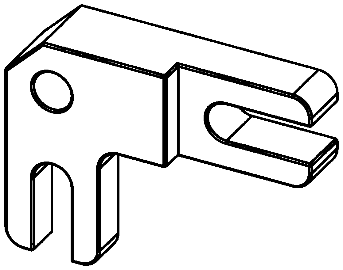
[0033] Both jaw links 3 are L-shaped structures, and each L-shaped structure is composed of two straight arms, and the free ends of the two straight arms of each L-shaped structure are provided with U-shaped grooves 3-3, and each The notches of a U-shaped groove 3-3 are towards the f...
specific Embodiment approach 2
[0043] Specific embodiment 2: This embodiment is a further description of the jaw structure that enables precise positioning of the pointer described in specific embodiment 1. In this embodiment, the jaw cylinder assembly 1 is used to start or close the cylinder 1-1 The switches 1-4 are magnetic switches.
specific Embodiment approach 3
[0044] Specific embodiment three: This embodiment is to further explain the structure of the jaws that can accurately position the pointer described in specific embodiment one. In this embodiment, the top of the jaw 5 is provided with a rectangular protrusion 5-1, a rectangular The protrusion 5-1 can be embedded in the rectangular groove 6.
PUM
 Abstract
Description
Claims
Application Information
 - R&D Engineer
- R&D Manager
- IP Professional
- Industry Leading Data Capabilities
- Powerful AI technology
- Patent DNA Extraction
Browse by: Latest US Patents, China's latest patents, Technical Efficacy Thesaurus, Application Domain, Technology Topic, Popular Technical Reports.
© 2024 PatSnap. All rights reserved.Legal|Privacy policy|Modern Slavery Act Transparency Statement|Sitemap|About US| Contact US: help@patsnap.com