
Injection molding device used for production of plastic products

A technology for plastic products and injection rods is applied in the field of injection molding devices for the production of plastic products. Time, reduce the time required for melting, and the effect of not easy to heat and melt

Inactive Publication Date: 2020-02-21
南通塑之源科技有限公司
View PDF0 Cites 2 Cited by
  • Summary
  • Abstract
  • Description
  • Claims
  • Application Information

AI Technical Summary

Problems solved by technology

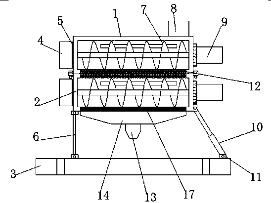
[0003] In the process of realizing the present invention, the inventor found that the following problems in the prior art have not been solved: 1. The existing device does not have the function of peeling off the outer layer of the material, which causes the molten part of the material to be mixed with the hard core of the unmelted material, resulting in The heating rate of the hard core of the material decreases, which affects the melting efficiency of the material; 2. The existing device does not have the function of recycling the remaining material. Due to the small amount of the remaining material, manual recovery is difficult, and most of the partially solidified material is pried out before secondary processing. The contact surface of the thick material that is difficult to handle in the box is reduced, the heating effect is poor, and the time required for the preheating process increases, etc.

Method used


Image

  • Injection molding device used for production of plastic products
  • Injection molding device used for production of plastic products

Examples


Embodiment Construction

[0019] In order to make the technical means, creative features, goals and effects achieved by the present invention easy to understand, the present invention will be further described below in conjunction with specific embodiments.

[0020] In describing the present invention, it should be understood that the terms "upper", "lower", "front", "rear", "left", "right", "top", "bottom", "inner", " The orientation or positional relationship indicated by "outside", etc. is based on the orientation or positional relationship shown in the drawings, and is only for the convenience of describing the present invention and simplifying the description, rather than indicating or implying that the referred device or element must have a specific orientation, so as to Specific orientation configurations and operations, therefore, are not to be construed as limitations on the invention.

[0021] In the description of the present invention, it should be noted that, unless otherwise specified and...


PUM


Abstract

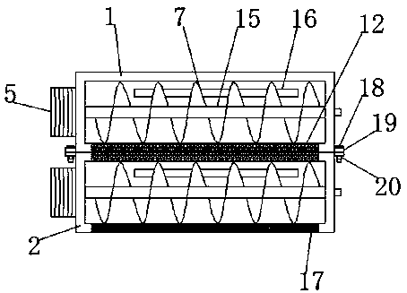
The invention discloses an injection molding device used for the production of plastic products. The injection molding device comprises a coarse material box, a fine material box is arranged at the bottom part of the coarse material box, injection molding rods are arranged in the middle parts of the coarse material box and the fine material box, the outer sides of the injection molding rods are fixedly provided with feeding screws, the top parts of the inner back wall in the coarse material box and the fine material box are fixedly provided with electric heating pipes, driving motors are fixedly arranged on the right outer walls of the coarse material box and the fine material box, and the injection molding rods penetrate through the right walls of the coarse material box and the fine material box. According to the injection molding device used for the production of the plastic products, a coarse screen and a fine screen are arranged, during the material heating and injection molding,the feeding screws of the injection molding rods can be driven to rotate through the driving motors, the outer layer of the materials is heated to melt, during the feeding screws driving the melted materials to move, the outer layer of the partially melted materials is extruded by the coarse screen to flow to the lower side of the coarse screen, in the same way, the fine screen can separate the outer layer of the materials twice, so that the heating rate of the hard core in the inner parts of the materials is improved, the time required for melting is reduced, and the injection molding deviceis suitable for extensive promotion and use.

Description

technical field [0001] The invention relates to the technical field of plastic product production equipment, in particular to an injection molding device for plastic product production. Background technique [0002] At present, injection molding machines are also known as molding machines or injection machines. It is the main molding equipment for making thermoplastics or thermosetting plastics into various shapes of plastic products with plastic molding molds. It is divided into vertical, horizontal, and all-electric types. The injection molding machine can heat the plastic and apply high pressure to the molten plastic. Injection fills the mold cavity. [0003] In the process of realizing the present invention, the inventor found that the following problems in the prior art have not been solved: 1. The existing device does not have the function of peeling off the outer layer of the material, which causes the molten part of the material to be mixed with the hard core of the...

Claims


Application Information

Patent Timeline
Patent Type & Authority Applications(China)
IPC IPC(8): B29C45/03B29C45/48B29C45/18B29C45/74B29B13/10
CPCB29B13/10B29C45/03B29C45/18B29C45/48B29C45/74
Inventor 汪发兵
Owner 南通塑之源科技有限公司
Learn More