Reducer capable of buffering landing and using method

A technology of a reducer and a landing cabin, applied in the aerospace field, can solve problems such as waste, achieve the effect of avoiding adverse effects and expanding the use value

Inactive Publication Date: 2020-02-21
徐芝香
View PDF0 Cites 1 Cited by
  • Summary
  • Abstract
  • Description
  • Claims
  • Application Information

AI Technical Summary

Problems solved by technology

In this technology, jettisoning the parachute is a complicated process and causes waste

Method used


Image

  • Reducer capable of buffering landing and using method
  • Reducer capable of buffering landing and using method
  • Reducer capable of buffering landing and using method

Examples


Embodiment Construction

[0028] It should be noted that, in the case of no conflict, the embodiments of the present invention and the technical features in the embodiments can be combined with each other. The present invention will be described in detail below with reference to the accompanying drawings and examples.

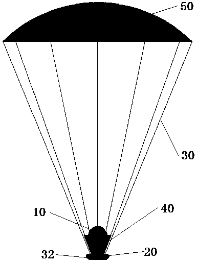
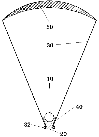
[0029] Such as figure 1 and figure 2 As shown, it is described that the umbrella canopy 50 has been opened to form a resistance surface to decelerate the spacecraft when entering the orbit; while the airbag 40 is in a retracted state. In the figure, there are 12 traction ropes 30 in total. One end of each traction rope 30 is tied to the edge of the umbrella canopy 50 , and the other end is tied to the rope retractor 32 . The resistance formed by the canopy 50 is finally transmitted to the base 20 . The base 20 carries the rope retractor 32 , the airbag 40 , the gas generator, and the landing module 10 ; the airbag 40 is located between the landing module 10 and the base 20 .

[0030...


PUM


Abstract

The invention relates to the technical field of aerospace, and relates to a reducer capable of buffering landing. The technical problem is the defects of an existing speed reduction technology. The technical scheme is that a drag parachute is wrapped around the outer periphery of a landing cabin. The reducer comprises a parachute canopy, traction ropes, rope gathering devices, a base and the landing cabin; the rope gathering devices are fixedly connected to the periphery of the base and can be controlled to gather and disperse the traction ropes; the landing cabin is fixedly connected to the base; and when the parachute canopy is opened, the rope gathering devices can gather the traction ropes, so that the parachute canopy is wrapped around the landing cabin. The reducer has the beneficialeffects that 1), when the landing cabin lands, the parachute canopy and an airbag are wrapped around the landing cabin, so that the protection is provided to the landing cabin; and 2), compared withthe existing drag parachute combined inflatable speed reduction technology, the scheme has the advantages that the drag parachute does not need to be discarded in the landing process, so that the adverse effect, caused by the fact that the drag parachute is discarded, on the landing cabin is avoided, the use value of the drag parachute is expanded, and the cost of transporting substances from theearth to an external planet is high.

Description

technical field [0001] The invention relates to the field of aerospace technology, and relates to a reducer capable of cushioning landing and a use method thereof. Background technique [0002] Spacecraft entry technology refers to the technology in which a spacecraft enters the atmosphere of an alien planet based on set requirements and then softly lands on the surface of the planet. It usually includes the following stages: 1. Departing from the orbit; 2. Transition into the transition period; 3. Entering the atmosphere; When entering the orbit, the spacecraft needs to be decelerated so that the spacecraft can land softly on the surface of the planet; among them, the existing deceleration parachute combined inflatable deceleration is a feasible technology; for example, the landing process of the Opportunity Mars rover in the United States is as follows: Fold it on the surface of the lander. When the lander reaches the predetermined height under the action of the drogue pa...

Claims


Application Information

Patent Timeline
Patent Type & Authority Applications(China)
IPC IPC(8): B64G1/62
CPCB64G1/62
Inventor 邱世军
Owner 徐芝香
Why Eureka
Try Eureka