Prefabricated wall body installing structure

A technology for installing structures and prefabricated walls, which is applied in the direction of walls, building components, building structures, etc., can solve the problems of slow installation speed of scaffolding or scaffolding, reduced construction speed, and hidden safety hazards, so as to facilitate concrete pouring and improve Safety and stability improvement effects

Active Publication Date: 2020-02-21
林州市汇鑫安装工程有限公司
View PDF6 Cites 5 Cited by
  • Summary
  • Abstract
  • Description
  • Claims
  • Application Information

AI Technical Summary

Problems solved by technology

[0003] When the existing prefabricated walls are assembled and constructed on site, the prefabricated walls are usually connected to the floor by means of cast-in-place concrete joints, which requires a large amount of wet work and requires the erection of a large number of external scaffolding or scaffolding, scaffolding or scaffolding The installation speed is slow, which reduces the construction speed, and there are safety hazards, so there is room for improvement

Method used


Image

  • Prefabricated wall body installing structure
  • Prefabricated wall body installing structure
  • Prefabricated wall body installing structure

Examples


Embodiment Construction

[0035] The present invention will be described in further detail below in conjunction with the accompanying drawings.

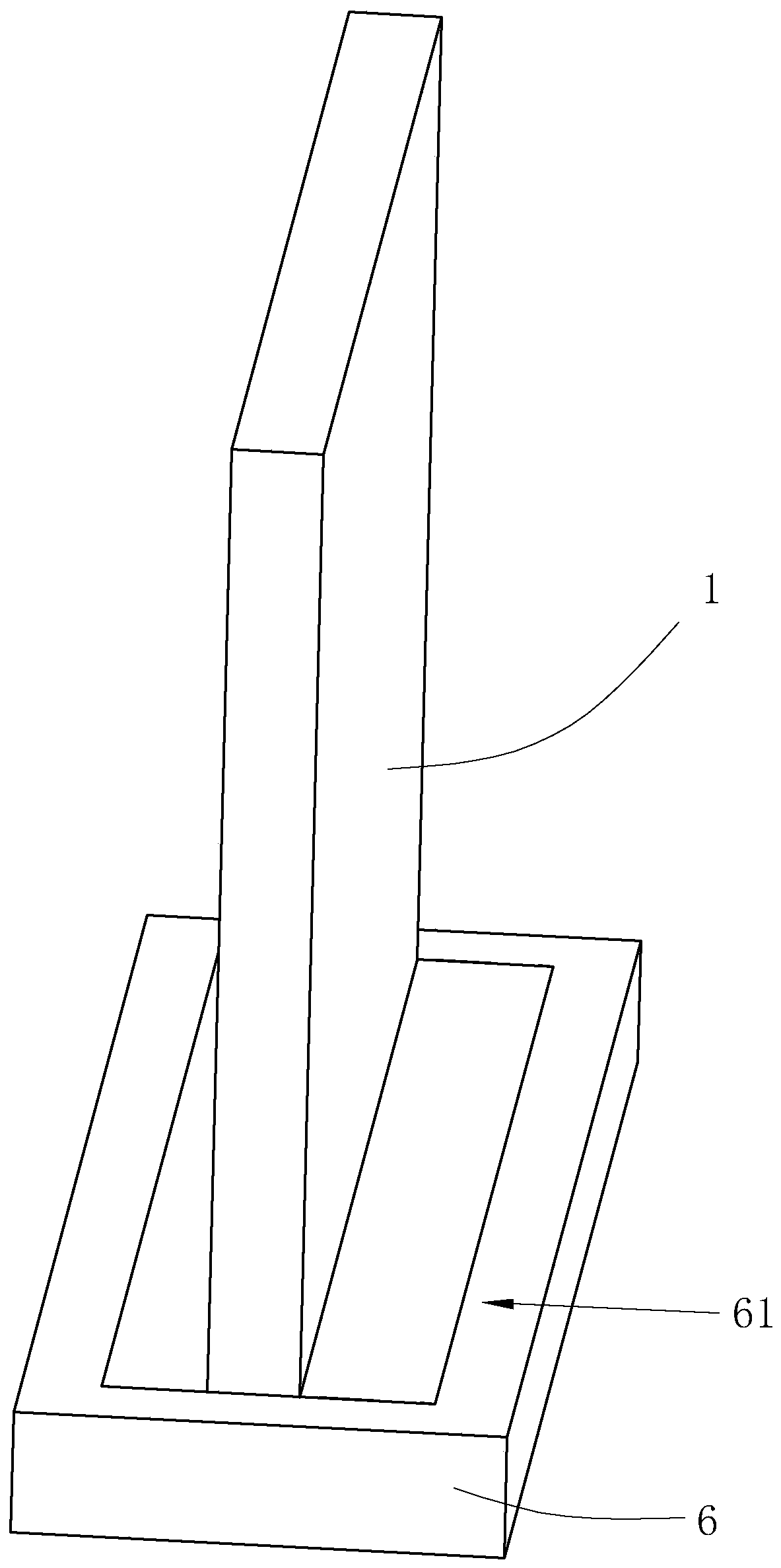
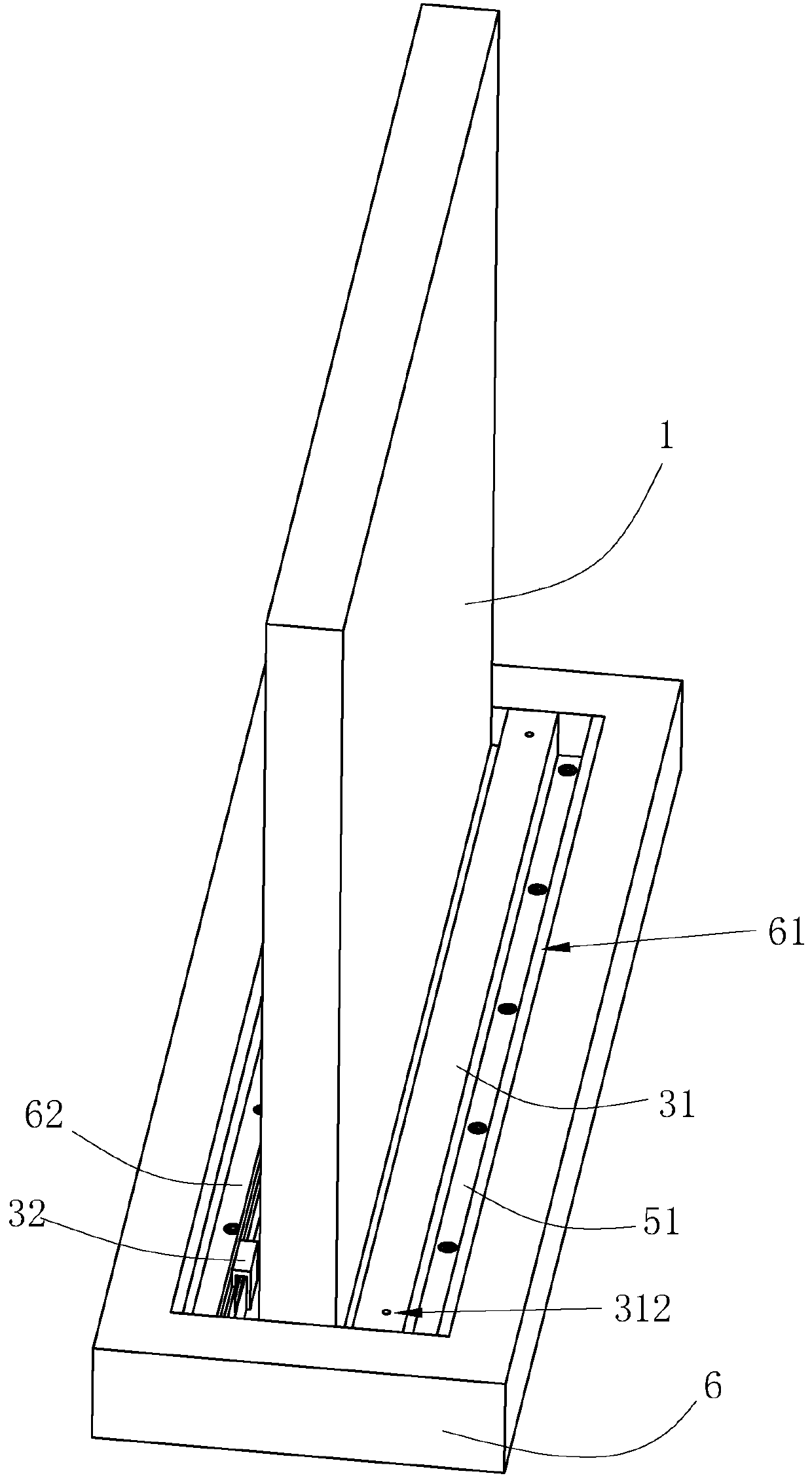
[0036] Such as Figure 1 to Figure 2 As shown, a prefabricated wall installation structure disclosed in the present invention is used to connect the prefabricated wall panel 1 with the floor 6, wherein the prefabricated wall installation structure is buried in the sinker 61 preset on the bottom plate 33, and the To quickly connect the prefabricated wall panel 1 and the floor 6 and support the positioning, and then realize the connection of the prefabricated wall panel 1 and the floor 6 by pouring concrete into the sinker 61 of the floor 6, thereby reducing the need for scaffolding and support racks The use of it improves the installation efficiency and reduces the production cost.

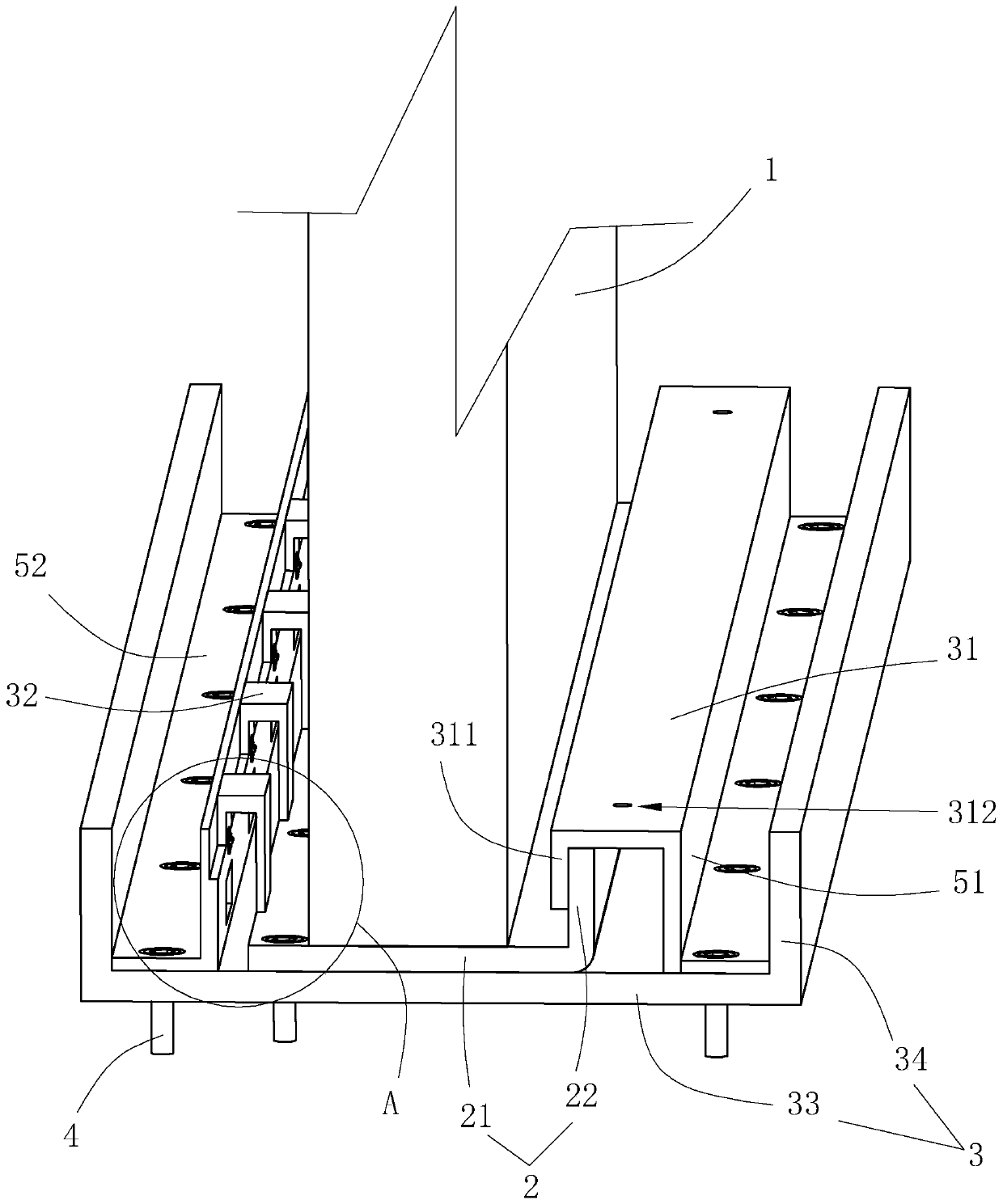
[0037] Such as Figure 2 to Figure 3As shown, the prefabricated wall installation structure includes an "L"-shaped connector 2 that is detachably fixed on the lower end surface ...


PUM


Abstract

The invention relates to a prefabricated wall body installing structure which comprises a connecting head and a connecting seat, wherein the connecting head is detachably connected onto the bottom endof a prefabricated wallboard; the connecting seat is fixed on a floorboard; the connecting head comprises a support plate parallel to the bottom surface of the prefabricated wallboard; a positioningplate is fixed at the upper end surface, positioned at one side of the prefabricated wallboard, of the support plate in a protruding way; the connecting seat is fixedly provided with a first positionlimiting plate in abut joint with the upper end surface of the positioning plate; the connecting seat is also elastically hinged to a second position limiting plate for tightly pressing the side, faraway from the positioning plate, of the support plate; and the connecting seat and the connecting head are embedded in a sink groove pre-formed in the floorboard. Through such arrangement, when the prefabricated wallboard is installed and connected with the connecting seat, the positioning plate turns to a position under the first position limiting plate; meanwhile, the side, far away from the positioning plate, of the support plate extrudes and turns to a position under the second position limiting plate, so that the positioning plate is tightly pressed through the first position limiting plate; and meanwhile, the second position limiting plate elastically resets to a state of tightly pressing the side, far away from the positioning plate, of the support plate, so that the goal of greatlyshortening the construction period is achieved.

Description

technical field [0001] The invention relates to the technical field of prefabricated buildings, in particular to a prefabricated wall installation structure. Background technique [0002] At present, in prefabricated buildings, the prefabricated walls produced by the factory are usually transported to the construction site for assembly, which enables some prefabricated walls to be produced in factories and greatly improves the efficiency of construction operations. [0003] When the existing prefabricated walls are assembled and constructed on site, the prefabricated walls are usually connected to the floor by means of cast-in-place concrete joints, which requires a large amount of wet work and requires the erection of a large number of external scaffolding or scaffolding, scaffolding or scaffolding The installation speed is slow, which reduces the construction speed, and there are safety hazards, so there is room for improvement. Contents of the invention [0004] In vie...

Claims


Application Information

Patent Timeline
Patent Type & Authority Applications(China)
IPC IPC(8): E04B1/61E04B2/82
CPCE04B1/6108E04B1/6112E04B1/612E04B2/821E04B2001/6195
Inventor 高志岗孙秀奇高晓平
Owner 林州市汇鑫安装工程有限公司
Why Eureka
Try Eureka