Transformer vacuum oil injection system

A transformer and vacuum technology, applied in the field of transformers, can solve problems such as excessive oil pressure, fast oil filling speed, overflow of transformer oil to the leakage pipeline, etc., and achieve the effect of tight logic and good effect

Pending Publication Date: 2020-02-21
LIRUITE ELECTRIC CO LTD
View PDF0 Cites 5 Cited by
  • Summary
  • Abstract
  • Description
  • Claims
  • Application Information

AI Technical Summary

Problems solved by technology

At present, the general oiling method for oil-immersed transformers is to directly pour transformer oil into the oil tank from the oiling nozzle on the tank cover. This oiling method has the advantages of simple operation and no need for complicated equipment and pipelines. Some water and a lot of air are mixed in, and it needs to be left for a long time after oil filling to allow the internal air to be discharged, and it will also affect the moisture discharge inside the oil tank and reduce the insulation strength of the transformer oil
[0003] At the same time, there are also some common transformer vacuum oiling devices on the market. These vacuum oiling devices use vacuum pressure to press the oil in the oil storage tank into the transformer. The vacuum pressure itself is relatively high, and the oil pressure is too high during the oil filling process, which leads to the oil filling speed being too fast, and air bubbles are easily generated in the transformer oil tank; at the same time, because the power of oil filling itself uses vacuum pressure, when the transformer oil tank is about to be filled, It is difficult for the operator to control the transformer oil tank to be in a state of just being full. Often, the transformer oil tank is not filled or the transformer oil overflows into the leakage pipeline. It is very inconvenient to operate and clean up, and it is time-consuming and laborious.
[0004] In addition, the existing vacuum oiling device for transformers is not separated into two modules for logically tight operation in terms of vacuuming and oiling. The error in the overall operation is large, and the oiling can not meet the requirements of various complex situations.

Method used


Image

  • Transformer vacuum oil injection system
  • Transformer vacuum oil injection system
  • Transformer vacuum oil injection system

Examples


Embodiment Construction

[0026] Specific examples are given below to further describe the technical solution of the present invention in a clear, complete and detailed manner. This embodiment is the best embodiment on the premise of the technical solution of the present invention, but the protection scope of the present invention is not limited to the following embodiments.

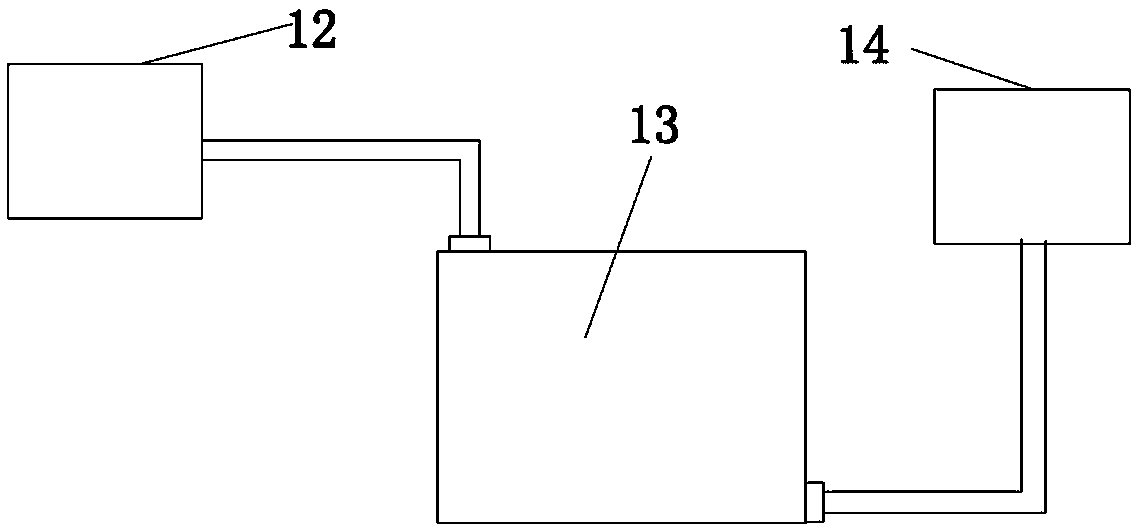
[0027] A transformer vacuum oiling system, comprising a vacuum part 12, a transformer 13 and an oil injection part 14 connected in sequence, the vacuum part 12 is connected to the upper end of the transformer 13, and the oil injection part 14 is connected to the lower end of the transformer 13;

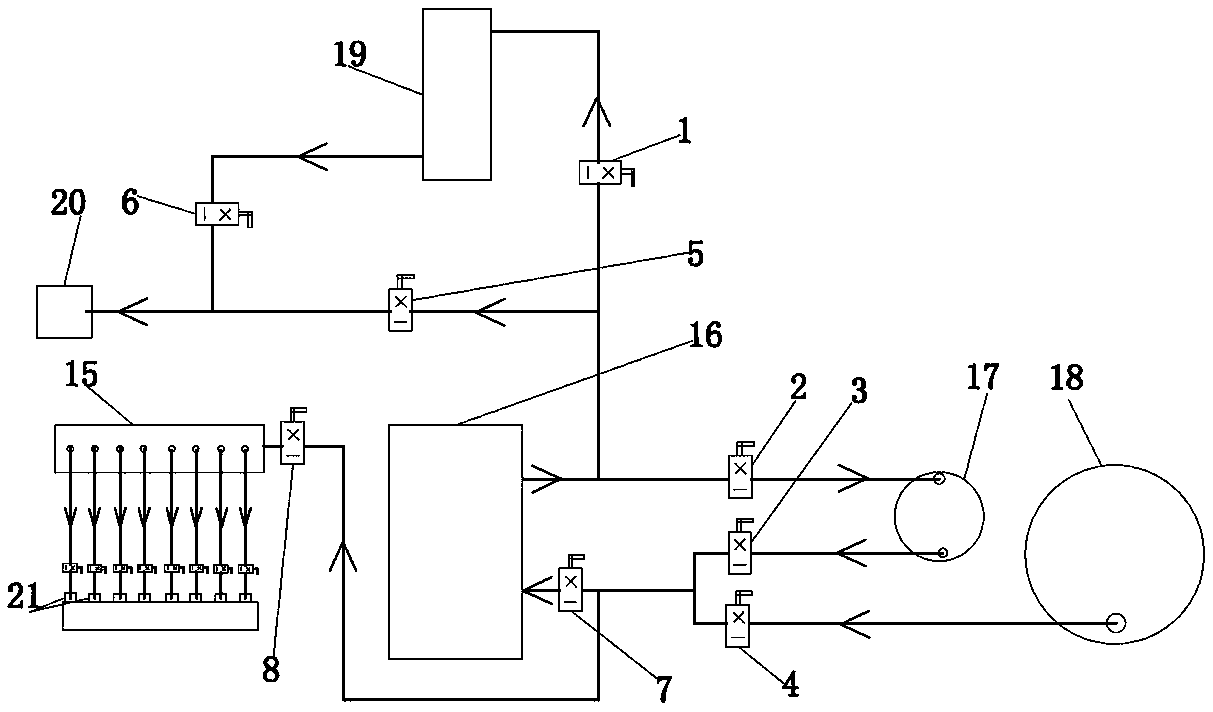
[0028] The oil injection part 14 includes a vacuum oil injection pipe 15, an oil filter unit 16, a first oil tank 17, a second oil tank 18, an oil supplement hanging tank 19, a first oil circuit, a second oil circuit, a third oil circuit, a Four oil circuits and the fifth oil circuit; the first oil tank 17 and the second oil tank 18 are ...


PUM


Abstract

The invention discloses a transformer vacuum oil injection system. The transformer vacuum oil injection system comprises a vacuumizing part, a transformer and an oil injection part which are connectedin sequence, the vacuumizing part communicates with the upper end of the transformer, and the oil injection part communicates with the lower end of the transformer; the oil injection part comprises avacuum oil injection pipe, an oil filter, a first oil tank, a second oil tank, an oil supplementing hanging tank, a first oil way, a second oil way, a third oil way, a fourth oil way and a fifth oilway. The first oil tank and the second oil tank both communicate with the oil filter, the second oil tank and the vacuum oil injection pipe communicate with the first oil tank, the oil supplementing hanging tank is connected with the oil filter and the first oil tank through communication pipelines, a transformer oil filling port is formed in the oil outlet of the oil supplementing hanging tank, and a vacuum oil filling port is formed in the vacuum oil injection pipe; all the modules are matched with one another, logic is tight, oil injection of the transformer under different using environments and requirements can be well met, integration of oil filtering, oil injection, vacuum oil injection and oil supplementing is achieved, and the vacuum oil injection effect is good.

Description

technical field [0001] The invention belongs to the technical field of transformers, and in particular relates to a transformer vacuum oiling system. Background technique [0002] As transformer oil has been widely used as the insulating medium and cooling medium of oil-immersed transformers, it is necessary to inject transformer oil after the oil-immersed transformer is assembled and sealed. At present, the general oiling method for oil-immersed transformers is to directly pour transformer oil into the oil tank from the oiling nozzle on the tank cover. This oiling method has the advantages of simple operation and no need for complicated equipment and pipelines. Some water and a lot of air are mixed in, and it needs to be left for a long time after oil filling to allow the internal air to be discharged. In addition, it will also affect the discharge of moisture inside the oil tank and reduce the insulation strength of the transformer oil. [0003] At the same time, there ar...

Claims


Application Information

Patent Timeline
Patent Type & Authority Applications(China)
IPC IPC(8): H01F27/14B67D7/72
CPCB67D7/72H01F27/14
Inventor 张华旭冯铎王安白冰洋李文喆随向前周罗鹏冯建海
Owner LIRUITE ELECTRIC CO LTD
Why Eureka
Try Eureka