
An automatic shaping device and shaping method for bonded magnet products

A technology of bonded magnets and products, which is applied in the manufacture of inductors/transformers/magnets, electrical components, circuits, etc., can solve problems such as low efficiency and precision, difficulty in shaping products, and high difficulty in shaping operations, so as to maintain ecological sustainability, The effect of high integer precision and reduced production cost

Active Publication Date: 2020-12-22
HENGDIAN GRP DMEGC MAGNETICS CO LTD
View PDF6 Cites 0 Cited by
  • Summary
  • Abstract
  • Description
  • Claims
  • Application Information

AI Technical Summary

Problems solved by technology

[0005] The present invention overcomes the low efficiency and precision of manual shaping processing in the prior art when the bonded magnetic product is shaped, the high temperature of the product during shaping leads to high difficulty in shaping operations, and the fact that the temperature of the product is relatively high. When it is high, it is difficult to shape, and the shape of the product after cooling cannot meet the technical problems of the expected shaping accuracy. An automatic shaping device and shaping method for bonded magnet products are provided. The shaping device passes the upper punch, the concave die, the The cooperation of the lower punch and the core realizes the automatic shaping of the bonded magnetic products. The shaping process is simple and efficient. In addition, the cooling liquid performs synchronous cooling on the high-temperature bonded magnetic products during the shaping process. After the molding is completed, the bonded magnetic product at room temperature will not undergo secondary deformation, and the shaping accuracy of the shaping device is relatively high

Method used


Image

  • An automatic shaping device and shaping method for bonded magnet products
  • An automatic shaping device and shaping method for bonded magnet products
  • An automatic shaping device and shaping method for bonded magnet products

Examples


Embodiment

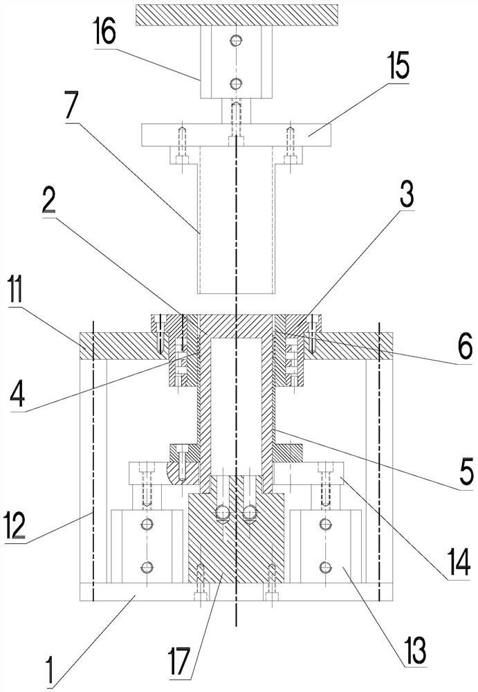
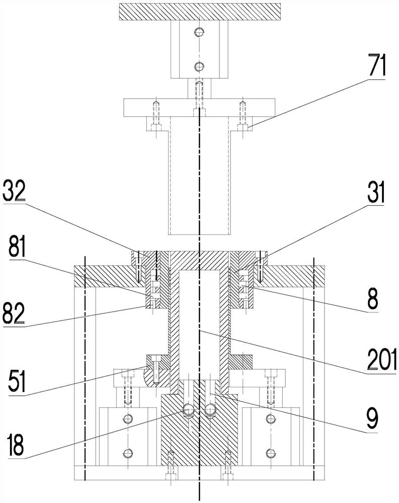
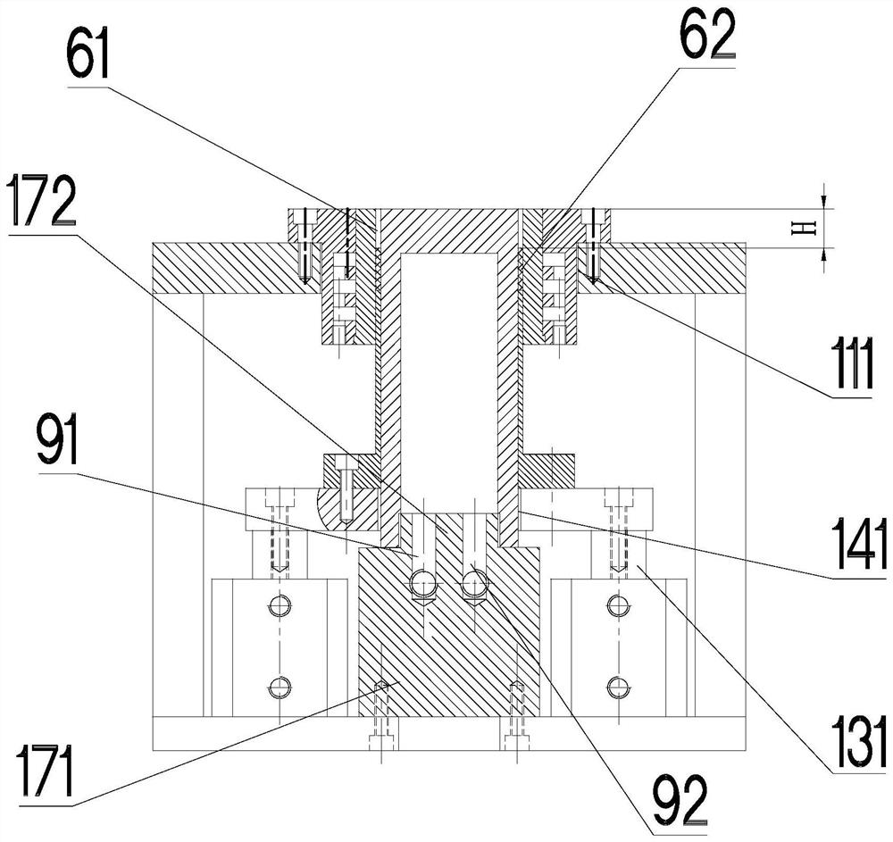
[0042] like Figure 1 to Figure 4 As shown, an automatic shaping device for bonded magnet products includes a bottom plate 1, a core 2 is fixedly connected to the bottom plate, and a die 3 is sleeved on the outer peripheral surface of the core with a radial gap between them. , the outer periphery of the core is provided with a lower punch 5 for carrying the product 4 to be shaped, and the bottom plate is provided with a driving member for driving the lower punch to slide back and forth along the length of the core, and the end of the lower punch away from the bottom plate is always Located inside the die, the upper end of the lower punch, the inner peripheral surface of the die and the outer peripheral surface of the core cooperate to form a plastic cavity 6 for plastic processing of the product to be shaped, and the upper punch located above the lower punch 7 Sliding axially along the ring-shaped shaping cavity, the die is provided with a first cooling channel 8 for cooling t...


PUM


Abstract

The embodiment of the invention discloses an automatic shaping device and method for a bonded magnet product, and aims at solving technical problems that in the prior art, when a bonded magnet productis shaped and machined, manual shaping and machining efficiency and precision are low, and the shape of the cooled product cannot meet the precision requirement. The device comprises a bottom plate,wherein a core is fixedly connected with the bottom plate, a female die is sleeved on an outer peripheral surface of the core, the periphery of the core is sleeved with a lower male die used for bearing a product to be shaped, a driving piece for driving the lower male die to slide back and forth is arranged on the bottom plate, an upper end of the lower male die, an inner circumferential face ofthe female die and an outer circumferential face of the core are matched to form a shaping cavity used for shaping a product to be shaped, the upper male die located above the lower male die slides inthe axial direction of the annular shaping cavity in a matched mode, the female die is provided with a first cooling water channel used for cooling a product to be shaped, the core is provided with asecond cooling water channel used for cooling the product to be shaped, and the first cooling water channel and the second cooling water channel are both connected with a cooling pool containing thecooling liquid.

Description

technical field [0001] The invention relates to the technical field of bonded magnet manufacturing, in particular to an automatic shaping device and shaping method for bonded magnet products. Background technique [0002] Bonded magnet refers to a magnet made by mixing magnetic powder with certain permanent magnetic properties and a certain proportion of binder according to a certain molding process; if an orientation magnetic field is applied during the molding process, the easy magnetization direction of the magnetic powder is in the In the same direction, this is an anisotropic bonded magnet, otherwise it is an isotropic magnet. There are various forming methods for bonded magnets, including compression molding, injection molding, extrusion molding, and calendering. After the bonded magnetic products are formed, they are sintered, sprayed, and placed, which are prone to out-of-roundness, large and small ends, and substandard dimensions. The remedy is to add another shapi...

Claims


Application Information

Patent Timeline
Patent Type & Authority Patents(China)
IPC IPC(8): H01F41/02
CPCH01F41/0246
Inventor 黄华为卢晓强张筝陈辉明
Owner HENGDIAN GRP DMEGC MAGNETICS CO LTD
Learn More