
Patsnap Eureka
For R&D, Patsnap Eureka makes reading and utilizing patents & technical documents easy.
Patsnap Eureka AIR
Designed for self-driven R&D workflows. Generate viable solutions, solve complex R&D challenges, empower your innovation with AI.

Patsnap Eureka Materials
Designed for material experts only. Revolutionize your material R&D, from search, analyze, to developing new materials.

TechResearch
Generate reliable direction feasibility study reports for your R&D in just a few steps.

TechSeek
Discover and master advanced knowledge NOW. Basics, ideas, possibilities, all at once.

TechMind
As an expert in R&D Theories, TechMind can generates customized viable solutions instantly.

TechRisk
Analyze your overall solution with one click, know your potential R&D risks in advance.

TechMonitor
Get weekly tech updates, stay abreast of the latest tech innovations and key insights.
Oil discharging system exhauster and oil discharging system
A technology of oil unloading system and exhaust device, which is applied in the field of oil transportation, can solve problems such as being discharged indoors, and achieve the effect of eliminating potential safety hazards and avoiding air resistance
- Summary
- Abstract
- Description
- Claims
- Application Information
AI Technical Summary
Problems solved by technology
Method used
Image

Examples
Embodiment Construction
[0021] In order to make the object, technical solution and advantages of the present invention clearer, the implementation manner of the present invention will be further described in detail below in conjunction with the accompanying drawings.
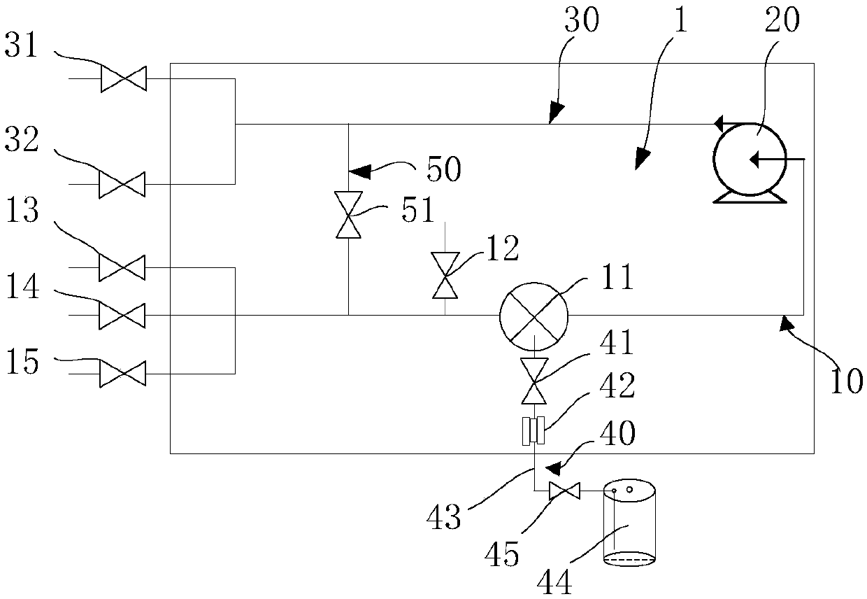
[0022] figure 1 It is a schematic diagram of an oil unloading system provided by an embodiment of the present invention. Such as figure 1 As shown, the oil unloading system includes an oil unloading circuit 1 . The oil unloading circuit 1 includes an oil inlet pipeline 10 , an oil pump 20 and an oil outlet pipeline 30 . The oil inlet pipeline 10, the oil pump 20 and the oil outlet pipeline 30 are connected in sequence.
[0023] Optionally, at least one stop valve is installed on the oil inlet pipeline 10 . For example, in figure 1 In the illustrated embodiment, there are three, namely the first cut-off valve 13 , the second cut-off valve 14 and the third cut-off valve 15 . The first shut-off valve 13, the second shut-off valve 14...
PUM
 Abstract
Description
Claims
Application Information
 - R&D Engineer
- R&D Manager
- IP Professional
- Industry Leading Data Capabilities
- Powerful AI technology
- Patent DNA Extraction
Browse by: Latest US Patents, China's latest patents, Technical Efficacy Thesaurus, Application Domain, Technology Topic, Popular Technical Reports.
© 2024 PatSnap. All rights reserved.Legal|Privacy policy|Modern Slavery Act Transparency Statement|Sitemap|About US| Contact US: help@patsnap.com