Bidirectional slip type hydraulic permanent packer

A packer and hydraulic technology, applied in sealing/packing, wellbore/well parts, earthwork drilling and production, etc., can solve problems such as long operation time, many processes, repeated processes, etc.

Active Publication Date: 2020-02-25
CHINA NAT PETROLEUM CORP CHUANQING DRILLING ENG CO LTD +1
View PDF7 Cites 4 Cited by
  • Summary
  • Abstract
  • Description
  • Claims
  • Application Information

AI Technical Summary

Problems solved by technology

[0003] There are many processes and long working hours, so it cannot be put into production in time
Oil testing generally includes more than ten steps such as drilling, wall scraping, running test strings, perforating, reservoir stimulation, blowout and fluid discharge, production testing, well killing, and testing strings. Including nearly ten steps such as secondary wellbore preparation, running the completion string, fluid replacement, setting, and blowout. Some wells even need secondary acidification to restore production capacity, which will take a lot of time
[0004] Since the packer used does not have the function of downhole drop-off and secondary tie-back, it is necessary to run the packer and the lower pipe string multiple times, resulting in repeated procedures, which is time-consuming and labor-intensive

Method used


Image

  • Bidirectional slip type hydraulic permanent packer
  • Bidirectional slip type hydraulic permanent packer
  • Bidirectional slip type hydraulic permanent packer

Examples


Embodiment Construction

[0036]Hereinafter, the two-way slip hydraulic permanent packer of the present invention will be described in detail with reference to the accompanying drawings and exemplary embodiments. It should be noted that "first", "second", "third", "fourth" and so on are only for convenience of description and distinction, and should not be understood as indicating or implying relative importance. "Up", "lower", "inner" and "outer" are only for the convenience of describing and constituting a relative orientation or positional relationship, and do not indicate or imply that the referred components must have the specific orientation or position.

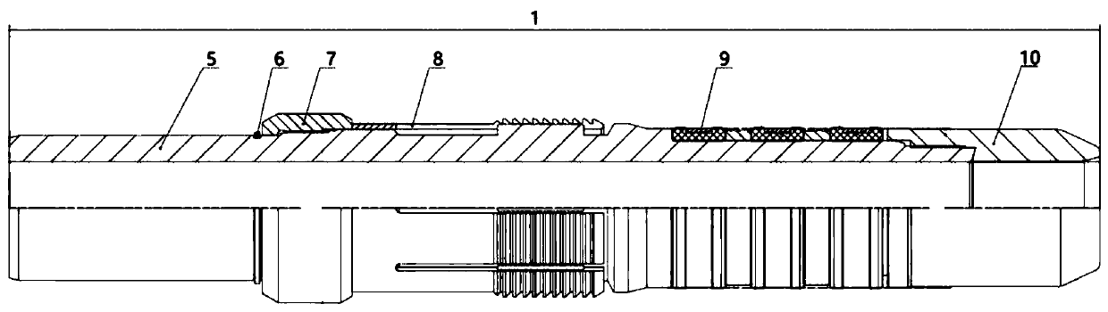
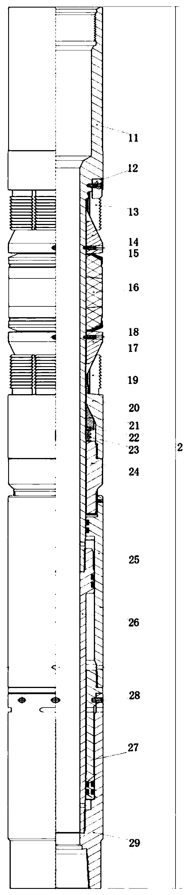
[0037] figure 1 A structural schematic diagram of an anchoring and sealing assembly of an exemplary embodiment of a two-way slip hydraulic permanent packer according to the present invention is shown. figure 2 A structural schematic diagram of an exemplary embodiment of a two-way slip hydraulic permanent packer according to the present invent...


PUM

PropertyMeasurementUnit
diameteraaaaaaaaaa
specific surface areaaaaaaaaaaa
diameteraaaaaaaaaa

Abstract

The invention provides a bidirectional slip type hydraulic permanent packer. The packer comprises an upper mandrel, a lower mandrel, an upper hydraulic outer cylinder, a lower hydraulic outer cylinder, a first shearing fixing piece, a second shearing fixing piece, a third shearing fixing piece, an upper slip, an upper cone, a rubber cylinder, a lower cone, a lower slip, a locking ring sleeve, an inner locking ring, a retaining piece, an elastic piece and an annular piston, wherein the upper slip, the upper cone, the rubber cylinder, the lower cone, the lower slip, the locking ring sleeve, theinner locking ring, the retaining piece and the elastic piece are sequentially arranged on the upper mandrel in a sleeving mode from top to bottom, and the annular piston is arranged on the lower mandrel in a sleeving mode; the lower end of the upper mandrel is connected with the upper end of the lower mandrel, and the lower end of the lower mandrel is connected with the lower hydraulic outer cylinder; the upper end of the upper slip is fixedly connected with the upper mandrel, the lower end of the upper slip is arranged on the conical surface of the upper cone in a sleeving mode, and the lower section of the upper cone is connected with the upper mandrel through the first shearing fixing piece; the rubber cylinder is arranged between the upper cone and the lower cone; the upper section ofthe lower cone is connected with the upper mandrel through the second shearing fixing piece; and the upper end of the lower slip is arranged on the conical surface of the lower cone in a sleeving mode. The packer has the advantages of bidirectional sealing, releasing, secondary tie-back and the like.

Description

technical field [0001] The invention relates to the technical field of well testing and completion equipment for oil and gas wells, in particular to a two-way slip hydraulic permanent packer. Background technique [0002] At present, the oil testing and completion operations of most exploration wells or evaluation wells need to be completed in two steps. The first step is to lower the test string with a series of tools such as packer, test valve, and electronic pressure gauge to the vicinity of the production layer, and then conduct a blowout production test. After the test, kill the well, pull the string and temporarily plug , this step is mainly for the purpose of obtaining formation data; if there is production and the well needs to be completed and put into production, it will be transferred to the second step, and the wellbore preparation (including drilling plug, wall scraping, well drilling, etc.) Completion strings for a series of tools such as separators and downho...

Claims


Application Information

Patent Timeline
Patent Type & Authority Applications(China)
IPC IPC(8): E21B33/128E21B33/129E21B33/12C08L15/00C08K13/04C08K3/04C08K3/34C08K7/26
CPCC08K3/04C08K3/34C08K7/26C08K13/04E21B33/1204E21B33/1208E21B33/1285E21B33/1293E21B33/1295C08L15/005
Inventor 谢胜黄船陈华良贺秋云贾海蔡佳成舒梅周继东林锐潘登刘兴华岳星辰
Owner CHINA NAT PETROLEUM CORP CHUANQING DRILLING ENG CO LTD
Why Eureka
Try Eureka