A Nanofluid Heat Collector with Helically Strengthened Heat Pipes

A nano-fluid, spiral-shaped technology, applied in the field of solar heat exchange, can solve the problems of high heat dissipation rate, blockage of micro-channels, and difficult manufacturing, and achieve the effect of improving heat collection efficiency, reducing heat loss and reducing heat loss.

Active Publication Date: 2020-11-20
JIANGSU UNIV
View PDF3 Cites 4 Cited by
  • Summary
  • Abstract
  • Description
  • Claims
  • Application Information

AI Technical Summary

Problems solved by technology

[0003] The patent document (CN 1932410A) proposes a nanofluid solar window collector. Its main scheme is to use different nanofluids to utilize solar radiation in sub-bands, multi-forms, and all-bands. However, the disadvantage of this method is that the heat dissipation rate is too high. High, can not achieve the purpose of heat collection
[0004] The patent document (CN 203813716 U) proposes a cooling high-power concentrating solar photovoltaic thermal system based on nanofluid microchannels. The main solution is to use nanofluid microchannel subsystem cooling methods to achieve high-efficiency photovoltaic effects, but This method has the disadvantage of nanofluid clogging the microchannel
[0005] The patent document (CN 102434981 A) proposes a flat-plate heat pipe collector, the main solution of which is to use a flat-plate heat pipe collector to achieve efficient utilization of solar energy, but this method has the disadvantages of high manufacturing difficulty and weak theoretical basis
[0006] It can be seen from the current situation that there are currently no products with a high comprehensive performance index in the solar collector market, and further research and improvement of technology is very important

Method used


Image

  • A Nanofluid Heat Collector with Helically Strengthened Heat Pipes
  • A Nanofluid Heat Collector with Helically Strengthened Heat Pipes

Examples


Embodiment Construction

[0030] In order to make the object, technical solution and advantages of the present invention clearer, the present invention will be further described in detail below in conjunction with the accompanying drawings and embodiments. It should be understood that the specific embodiments described here are only used to explain the present invention, not to limit the present invention.

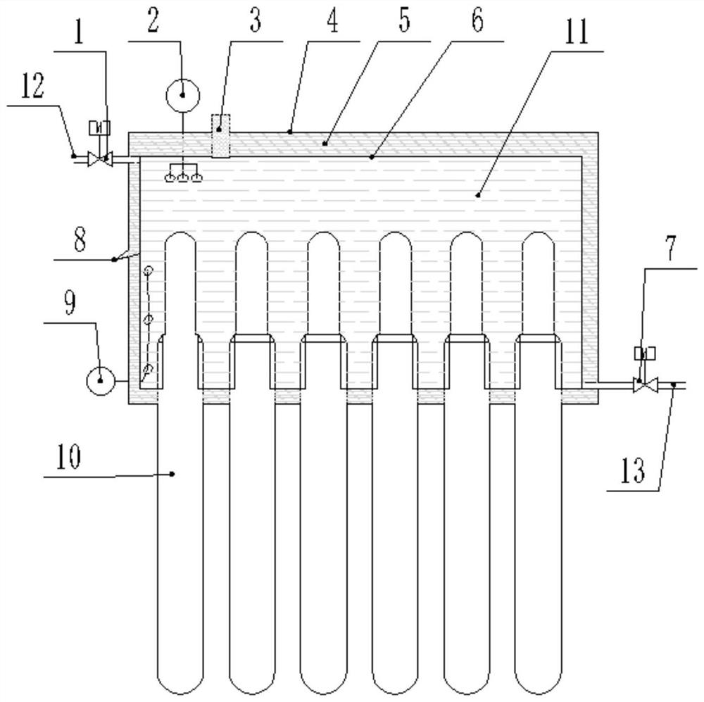
[0031] Such as figure 1 As shown, a nanofluid heat collector with a spiral reinforced heat pipe designed by the present invention includes a phase change heat storage tank 8 and a heat collection unit, the heat storage tank inner wall 6 of the phase change heat storage tank 8 and the heat storage tank There is an insulating layer between the outer walls 4, and an insulating material 5 is filled in the insulating layer. In this embodiment, the insulating material 5 can be mineral wool or rock wool, and the thickness of the insulating layer is 40mm to 50mm, which can ensure a stable heat storage capa...


PUM

PropertyMeasurementUnit
diameteraaaaaaaaaa
thicknessaaaaaaaaaa
solar absorptanceaaaaaaaaaa

Abstract

The invention discloses a nanometer-fluid heat collector with a spiral-shaped reinforced heat pipe. The nanometer-fluid heat collector comprises a phase change heat storage box and a heat collection unit. The heat collection unit comprises one or more vacuum heat conduction pipes. The vacuum heat conduction pipes comprise closed heat pipes. Heat collection layers sleeve one ends, namely, the heatpipe evaporation ends, of the heat pipes. The other ends, namely, heat pipe condensation ends, of the heat pipes are inserted into the phase change heat storage box. Spiral reinforced condensers are arranged in the heat pipes. The heat pipes are filled with nanometer fluid as a heat conduction working medium. According to the nanometer-fluid heat collector with spiral-shaped reinforced heat pipe,the solar heat collection efficiency can be effectively improved by taking the nanometer fluid as the working medium.

Description

technical field [0001] The invention belongs to the technical field of solar energy heat exchange, in particular to a nanofluid heat collector with a spiral reinforced heat pipe. Background technique [0002] As an ideal clean energy, solar energy has dual significance for environmental protection and energy utilization. At present, the fields of utilization of solar energy mainly include photovoltaic power generation, thermal power generation and direct heat utilization. The limitation is that solar energy can only be utilized during the day, and the conversion efficiency is very low. Therefore, improving solar heat collection efficiency is one of the important ways to solve these limitations. [0003] The patent document (CN 1932410A) proposes a nanofluid solar window collector. Its main scheme is to use different nanofluids to utilize solar radiation in sub-bands, multi-forms, and all-bands. However, the disadvantage of this method is that the heat dissipation rate is to...

Claims


Application Information

Patent Timeline
Patent Type & Authority Patents(China)
IPC IPC(8): F24S10/95F24S70/20F24S80/65F24S80/00
CPCF24S10/95F24S70/20F24S80/00F24S80/65Y02E10/44
Inventor 李博刘添旺台颖娣程驰王军锋
Owner JIANGSU UNIV
Why Eureka
Try Eureka