Thimble type micro-impulse applying device

An application device and thimble-type micro-technology, which is applied in the field of precision mechanics, can solve the problems of inability to accurately adjust the size of the applied micro-impulse, large resistance, and poor stability, and achieve the effects of small resistance, reduced frictional damping, and small contact area

Inactive Publication Date: 2020-02-25
INNOVATION ACAD FOR MICROSATELLITES OF CAS +1
View PDF6 Cites 4 Cited by
  • Summary
  • Abstract
  • Description
  • Claims
  • Application Information

AI Technical Summary

Problems solved by technology

[0004] The purpose of the present invention is to provide a thimble type micro-pulse applying device to solve the problems of poor stability and large resistance of the existing micro-pulse applying device
[0005] The object of the present invention is also to provide a thimble type micro-pulse application device to solve the problem that the existing micro-pulse application device cannot accurately adjust the size of the applied micro-pulse

Method used


Image

  • Thimble type micro-impulse applying device
  • Thimble type micro-impulse applying device
  • Thimble type micro-impulse applying device

Examples


Embodiment 1

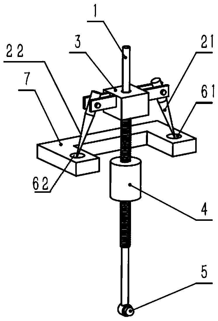
[0039] This embodiment provides a thimble type micro-pulse applying device, such as figure 1 As shown, the thimble type micro-pulse application device includes: a central rod 1, such as Figure 1~2As shown, the central rod 1 is at a balance position in a vertical position; the first thimble 21 and the second thimble 22 are symmetrically distributed with the central rod 1 as an axis. , the first thimble 21 and the second thimble 22 each have a needle point; the transfer structure 3, the transfer structure 3 connects the central rod 1 with the first thimble 21 and the second thimble 22 Fixed connection; the impact part 5, the impact part 5 is installed on the bottom of the central rod 1; the first bearing seat 61 and the second bearing seat 62, wherein: the first bearing seat 61 has a first concave arc surface , the tip of the first thimble 21 is in contact with the arc-shaped surface of the first recess, so that the first thimble 21 is placed on the first bearing seat 61, and ...


PUM


Abstract

The invention provides a thimble type micro-impulse applying device. The thimble type micro-impulse applying device comprises a center pole taking a vertical placing position as a balancing position;two thimbles symmetrically distributed by taking the center pole as an axis, wherein each thimble has a needle point; a switching structure for fixedly connecting the center pole with two thimbles; animpact part arranged at a lower part of the center pole; two bearing seats with pit curved surfaces, wherein two thimbles are placed on the bearing seats, the needle points of the thimbles are contacted with the pit curved surfaces; a bracket for horizontally placing two bearing seats, wherein two contact points of the needle points of the thimbles and the pit curved surfaces of the bearing seatscan be connected to form a horizontal line; the center of gravity of the center pole and the whole structure driven to swing by the center pole is lower than the horizontal line, the center pole canswing by taking the horizontal line as the rotating shaft, the contact area is small, and an aim of reducing the friction damping is realized. A balancing weight can rotatably change the height position on the center pole through thread matching, thereby changing the position located by the center of the gravity of the swing structure.

Description

technical field [0001] The invention relates to the technical field of precision mechanics, in particular to a thimble-type micro-pulse applying device. Background technique [0002] The application and precise measurement of micro-thrust and micro-impulse are of great significance to fields including aerospace propulsion and instrument and equipment manufacturing. [0003] The traditional way of applying tiny impulses to micro-impulse testing mechanisms is to use a knife-edge pendulum device: this device is often equipped with a force-sensitive sensor at the impact position. Specifically, the force-sensitive sensor is fixed to the swing arm, and the swing arm is pulled for a certain distance by a thin rope. After releasing it, due to the effect of gravity, the swing arm will drive the force-sensitive sensor to swing and hit the measured object. The force and time length of the knocking process can be output from the force sensitive sensor, so as to obtain the change of the...

Claims


Application Information

Patent Timeline
Patent Type & Authority Applications(China)
IPC IPC(8): G01M7/08
CPCG01L5/0052
Inventor 王彬朱洪斌张永合丁国鹏陈昕孙煜坤王亚敏
Owner INNOVATION ACAD FOR MICROSATELLITES OF CAS
Why Eureka
Try Eureka