Transposed conductor self-adhesion test clamping device

A technology of clamping device and transposition wire, which is applied in the field of wire test, can solve the problems of long overall time, inability to uniformly clamp and fix the transposition wire, low test efficiency, etc., and achieve simple structure, good self-adhesive test effect, and effective Good results

Pending Publication Date: 2020-02-25
徐州志欧机电设备有限公司
View PDF7 Cites 1 Cited by
  • Summary
  • Abstract
  • Description
  • Claims
  • Application Information

AI Technical Summary

Problems solved by technology

[0003] The transposition wire is composed of a certain number of enamelled copper flat wires into two rows in which the wide surfaces are in contact with each other, and the transposition of the same direction is made on the top and bottom of the two rows of enameled wires along the narrow surface as required, and an electrical insulating paper tape is used to It is made of multiple layers of continuous and tightly wrapped wires; after the production of the transposed wires, a self-adhesive test is required for the transposed wires, that is, the transposed wires are pressed tightly so that each composed of wires fits closely, and placed in a high temperature In the experimental equipment, the self-adhesive quality of the transposed conductor is judged by detecting the change of the self-adhesive paint of the conductor at high temperature. The existing test clamping device clamps and fixes the transposed conductor. And the number of transposed wires are uniformly clamped and fixed. When a small number of transposed wires are tested, the overall time under high temperature test is too long, and the test efficiency is low.

Method used


Image

  • Transposed conductor self-adhesion test clamping device

Examples


Embodiment Construction

[0014] The present invention will be further described below in conjunction with accompanying drawing.

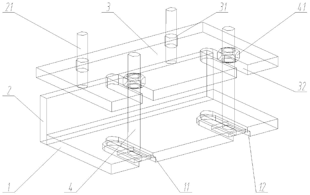
[0015] Such as figure 1 As shown, the clamping device for transposition wire self-adhesive test includes a bottom plate 1, a side plate 2, a top plate 3 and a limit post 4;

[0016] The side plate 2 is fixedly installed on the rear end of the bottom plate 1, and the top plate 3 is slidably arranged on the side plate 2 up and down, and is located above the bottom plate 1. The right end of the top plate 3 is provided with a front opening and a through groove 32 arranged front and rear. There are multiple grooves 32, and they are arranged left and right,

[0017] There are a plurality of limiting columns 4, which are arranged corresponding to the through grooves 32. The lower ends of the limiting columns 4 slide back and forth and are arranged on the bottom plate 1, the upper part passes through the through groove 32, and the upper part is locked and fixed by a locking device...


PUM


Abstract

The invention discloses a transposed conductor self-adhesion test clamping device. The transposed conductor self-adhesion test clamping device comprises a bottom plate (1), a side plate (2), a top plate (3) and limiting columns (4). The side plate (2) is fixedly arranged at the rear end of the bottom plate (1), the top plate (3) is arranged on the side plate (2) in an up-down sliding manner and ispositioned above the bottom plate (1), the right end of the top plate (3) is provided with a plurality of through grooves (32) with openings in the front ends and arranged front and back, the throughgrooves (32) are arranged left and right, the limiting columns (4) correspond to the through grooves (32), the lower ends of the limiting columns (4) are arranged on the bottom plate (1) in a front-back sliding mode, and the upper portions of the limiting columns (4) penetrate the through grooves (32) and are locked and fixed through locking devices. The transposed conductor self-adhesion test clamping device is simple in structure, achieves superposition and fixation of transposed conductors with different sizes and numbers, and enables the self-adhesion test effect to be better.

Description

technical field [0001] The invention relates to the field of wire testing, in particular to a clamping device for transposition wire self-adhesive testing. Background technique [0002] The transposition wire can greatly reduce the load loss, reduce the temperature rise of winding hot spots, improve the mechanical strength of the winding, make the structure more compact, and the coil processing is easier, so it is widely used in the design and manufacture of large-scale power transformer windings. [0003] The transposition wire is composed of a certain number of enamelled copper flat wires into two rows in which the wide surfaces are in contact with each other, and the transposition of the same direction is made on the top and bottom of the two rows of enameled wires along the narrow surface as required, and an electrical insulating paper tape is used to It is made of multiple layers of continuous and tightly wrapped wires; after the production of the transposed wires, a se...

Claims


Application Information

Patent Timeline
IPC IPC(8): G01N25/00B25B11/00
CPCB25B11/00G01N25/00
Inventor 孙辉
Owner 徐州志欧机电设备有限公司
Why Eureka
Try Eureka