
Visible laryngoscope

A laryngoscope and lens technology, applied in the field of visual laryngoscope, can solve problems such as unfavorable long-term use of the display screen, fogging of the camera, laborious plugging, etc., achieve broad market application prospects, prevent collision or wear, and prolong service life Effect

Pending Publication Date: 2020-02-28
纳智医疗设备(徐州)有限公司
View PDF0 Cites 0 Cited by
  • Summary
  • Abstract
  • Description
  • Claims
  • Application Information

AI Technical Summary

Problems solved by technology

[0003] With the help of some special equipment and inspection methods, laryngoscopes are generally used clinically to assist laryngeal examinations. Existing laryngoscopes will be equipped with a camera structure at the same time when equipped with a display screen. However, if there is a large difference between the air temperature and the oral temperature In some cases, it is easy to cause fogging of the camera, which is not conducive to observing the actual situation of the patient's larynx, and may lead to misjudgment. The mirror is placed on the medical placement table, which is not conducive to the long-term use of the display screen, and may cause collision or wear. Finally, the connection between the original arc arm and the lens is directly connected by grooves and convex grooves , the stability of this connection is poor, and it is more laborious to plug in at the same time, so the above problems are problems that need to be solved by technicians during the design and use of laryngoscopes

Method used


Image

  • Visible laryngoscope
  • Visible laryngoscope
  • Visible laryngoscope

Examples


Embodiment Construction

[0022] In order to enable those skilled in the art to better understand the solutions of the present invention, the technical solutions in the embodiments of the present invention will be clearly and completely described below in conjunction with the drawings in the embodiments of the present invention.

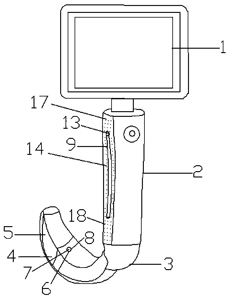
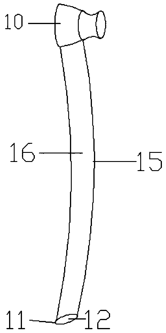
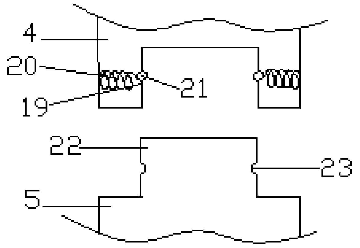
[0023] This embodiment provides a video laryngoscope, which includes a display screen 1, a hand-held part 2 and an extension part 3, and the extension part 3 includes an arc arm 4 and a lens 5, and the front end of the arc arm 4 is provided outside There is a camera hole 6, and a camera 7 is arranged inside the front end of the arc arm 4, and the camera direction of the camera 7 is toward the camera hole 6, and the outside of the camera 7 is covered with an anti-fog film 8, the The rear end of the arc-shaped arm 4 is connected to the hand-held part 2, the display screen 1 and the hand-held part 2 are connected to each other through rotation, and support rod structures 9 are ar...


PUM


Abstract

A visual laryngoscope comprises a display screen, a handheld part and an extending part. The extending part comprises an arc-shaped arm and a lens, wherein the arc-shaped arm and the lens are detachably connected; a camera shooting hole is formed in the outside of the front end of the arc-shaped arm, and a camera is arranged inside the front end of the arc-shaped arm; an anti-fog adhesive film coats the outside of the camera, and the rear end of the arc-shaped arm is connected with the handheld part; the display screen and the handheld part are connected with each other in a rotating manner; and supporting rod structures are arranged on two sides of the handheld part, and the whole supporting rod structures are made of rubber materials. A protruding cylindrical table structure is arrangedat the front end of each supporting rod structure; the rear end of each supporting rod is provided with a platform structure, and the upper end of the handheld part is provided with a round hole structure; the protruding cylindrical table structure is inserted into the round hole structure; and the handheld part is of a concave structure, and the inner side of each supporting rod structure is provided with a protruding structure matched with the concave structure.

Description

technical field [0001] The invention relates to a medical instrument, in particular to a video laryngoscope. Background technique [0002] Since the larynx is located relatively deep relative to the oral cavity, the physiological structure is complex and cannot be peeped directly. It is necessary to check the larynx [0003] With the help of some special equipment and inspection methods, laryngoscopes are generally used clinically to assist laryngeal examinations. Existing laryngoscopes will be equipped with a camera structure at the same time when equipped with a display screen. However, if there is a large difference between the air temperature and the oral temperature In some cases, it is easy to cause fogging of the camera, which is not conducive to observing the actual situation of the patient's larynx, and may lead to misjudgment. The mirror is placed on the medical placement table, which is not conducive to the long-term use of the display screen, and may cause colli...

Claims


Application Information

Patent Timeline
Patent Type & Authority Applications(China)
IPC IPC(8): A61B1/267A61B1/12A61B1/00
CPCA61B1/00066A61B1/00128A61B1/00131A61B1/127A61B1/267
Inventor 关洁莹
Owner 纳智医疗设备(徐州)有限公司
Learn More