Automatic cleaning device dedicated for bullet train insulator

A technology for cleaning equipment and insulators, which is applied in the field of machinery, can solve problems such as long scrubbing time, degradation of insulator insulation performance, and potential safety hazards, and achieve the effect of reducing manual output and improving efficiency

Inactive Publication Date: 2020-02-28
姜忠华
View PDF7 Cites 3 Cited by
  • Summary
  • Abstract
  • Description
  • Claims
  • Application Information

AI Technical Summary

Problems solved by technology

During the high-speed running of the motor car, the pantograph is in contact with the high-voltage voltage and receives electricity and friction, which is easy to ionize and generate a large amount of metal ions, which are deposited on the surface of the insulator used for insulation during the running process. After the metal ions are deposited on the surface of the insulator, it may form into flakes The metal film covering the surface of the insulator reduces the insulation performance of the insulator. During the driving process, these metal films are likely to cause arcs between the high-voltage wires and form a safety hazard.
[0003] At present, manual scrubbing is used to scrub the metal film on the surface of insulators, which is labor-intensive, takes a long time to scrub, and the scrubbing effect is unstable.

Method used


Image

  • Automatic cleaning device dedicated for bullet train insulator
  • Automatic cleaning device dedicated for bullet train insulator
  • Automatic cleaning device dedicated for bullet train insulator

Examples


Embodiment 1

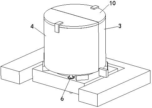
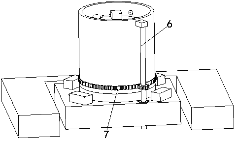
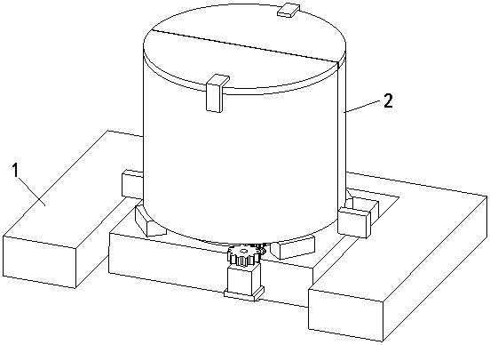
[0027] Embodiment 1: The present invention includes a card base 1, the card base 1 has a groove matching the shape of the insulator base, a cleaning cylinder 2 is fixed on the groove, and the cleaning cylinder 2 is fixed on the groove. The semi-cylinder 3 is composed of a movable semi-cylinder 4 that is movably connected with the fixed semi-cylinder 3. The ends of the fixed semi-cylinder 3 and the movable semi-cylinder have a joint closure structure that cooperates with each other. The opening of the fixed semi-cylinder 3 faces the opening of the groove. The fixed semi-cylinder 3 and the movable semi-cylinder 4 all include a semicircular shell and a semicircular inner container 5 positioned inside the outer shell, the inner container 5 and the outer shell are connected by a rotatable device, and the inner container 5 There is a cleaning device inside, at least one power gear shaft 6 is arranged between the inner tank 5 and the outer shell, and the outer wall of the inner tank 5...

Embodiment 2

[0034] Embodiment 2: The present invention includes a deck 1, the deck 1 has a groove matching the shape of the insulator base, a cleaning cylinder 2 is fixed on the groove, and the cleaning cylinder 2 is fixed on the groove. The semi-cylinder 3 is composed of a movable semi-cylinder 4 that is movably connected with the fixed semi-cylinder 3. The ends of the fixed semi-cylinder 3 and the movable semi-cylinder have a joint closure structure that cooperates with each other. The opening of the fixed semi-cylinder 3 faces the opening of the groove. The fixed semi-cylinder 3 and the movable semi-cylinder 4 all include a semicircular shell and a semicircular inner container 5 positioned inside the outer shell, the inner container 5 and the outer shell are connected by a rotatable device, and the inner container 5 There is a cleaning device inside, and three groups of rotating groups 11 that are evenly distributed around the axis of the cleaning cylinder 2 are arranged between the inn...


PUM


Abstract

The invention belongs to the technical field of machinery, relates to maintenance equipment for high-speed railway bullet trains and specifically relates to an automatic cleaning device dedicated fora bullet train insulator. The automatic cleaning device comprises a clamping base, wherein a groove matched with an insulator seat in shape is formed in the clamping base; a cleaning cylinder is fixedin the groove; the cleaning cylinder consists of a fixed semicircular cylinder fixed in the groove and a movable semicircular cylinder movably connected to the fixed semicircular cylinder; the fixedsemicircular cylinder and the movable semicircular cylinder each comprise a semicircular shell and a semicircular liner located on the inner side of the shell; each liner and the corresponding shell are connected by a rotatable device; a cleaning apparatus is disposed on the inner side of each liner; at least one power gear shaft is disposed between each liner and the corresponding shell; gear teeth matched with a gear on each power gear shaft are disposed on the outer wall of the corresponding liner; and the power gear shafts are rotatably fixed on the clamping base. The automatic cleaning device provided by the invention has the beneficial effects that manual output during cleaning is reduced and cleaning efficiency is increased through above automatic cleaning processes.

Description

technical field [0001] The invention belongs to the technical field of machinery, and relates to high-speed train maintenance equipment, in particular to a special automatic cleaning equipment for train insulators. Background technique [0002] As a kind of electrical equipment for the electric traction locomotive to obtain electric energy from the catenary, the high-speed train is installed on the roof of the locomotive or the train. The pantograph is composed of slide plate, upper frame, lower arm, underframe, bow spring, transmission cylinder, supporting insulator and other components. During the high-speed running of the motor car, the pantograph is in contact with the high-voltage voltage and receives electricity and friction, which is easy to ionize and generate a large amount of metal ions, which are deposited on the surface of the insulator used for insulation during the running process. After the metal ions are deposited on the surface of the insulator, it may form ...

Claims


Application Information

Patent Timeline
Patent Type & Authority Applications(China)
IPC IPC(8): B08B1/02B08B3/10B08B13/00
CPCB08B1/006B08B1/02B08B3/041B08B3/10B08B13/00
Inventor 姜忠华
Owner 姜忠华
Why Eureka
Try Eureka