Welding method of side parts of metal inner layer, flexible middle layer and metal outer layer of variable-type ultra-thin structure

A metal outer layer, welding method technology, applied in welding equipment, welding equipment, laser welding equipment and other directions, can solve the problem of inability to achieve reliable connection, and achieve high-strength and reliable connection, good sealing, no air leakage.

Active Publication Date: 2020-02-28
浙江普兴电子科技有限公司
View PDF6 Cites 0 Cited by
  • Summary
  • Abstract
  • Description
  • Claims
  • Application Information

AI Technical Summary

Problems solved by technology

[0005] The purpose of the present invention is to solve the problem that the side of the variable ultra-thin structure metal layer-flexible layer-metal layer cannot be reliably connected, and provide a variable ultra-thin structure metal inner layer-flexible middle layer-metal outer layer side welding method

Method used


Image

  • Welding method of side parts of metal inner layer, flexible middle layer and metal outer layer of variable-type ultra-thin structure
  • Welding method of side parts of metal inner layer, flexible middle layer and metal outer layer of variable-type ultra-thin structure
  • Welding method of side parts of metal inner layer, flexible middle layer and metal outer layer of variable-type ultra-thin structure

Examples


specific Embodiment approach 1

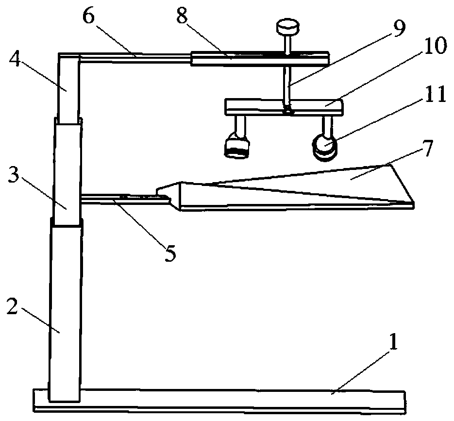
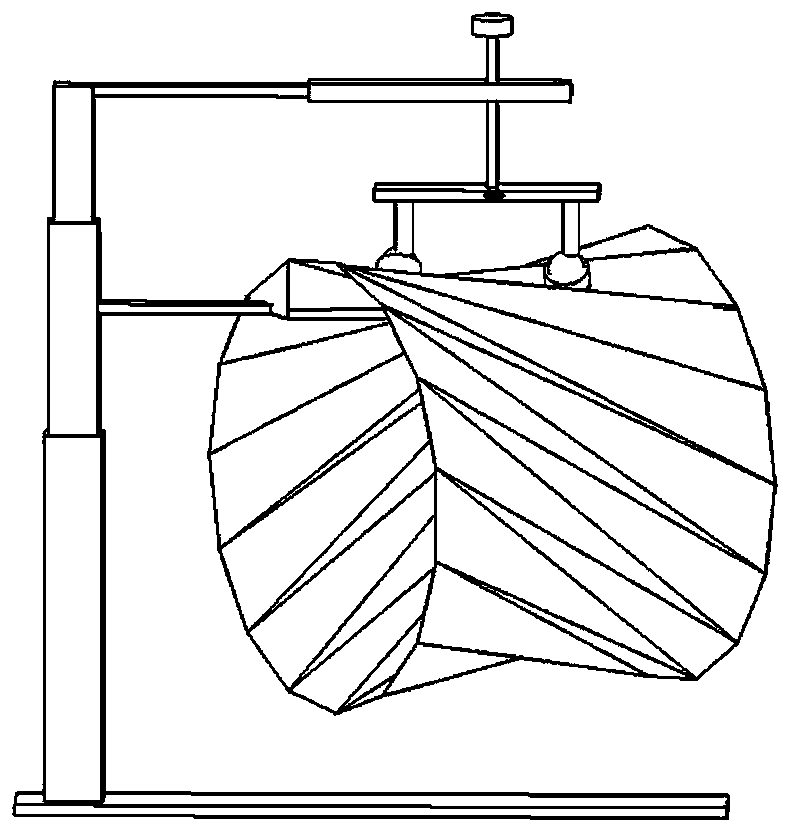
[0018] Specific implementation mode 1: This implementation mode is a welding method for the side part of the variable ultra-thin structure metal inner layer-flexible middle layer-metal outer layer, which is specifically completed according to the following steps:

[0019] 1. Metal inner layer welding: use clamps to clamp the metal inner layer joint of the variable ultra-thin structure, and then use laser to weld the weld seam of the metal inner layer joint to obtain the variable ultra-thin structure of the metal inner layer welding;

[0020] 2. Wrapping the flexible middle layer: Wrapping the flexible middle layer on the outer surface of the metal inner layer of the variable-shaped ultra-thin structure welded to the metal inner layer, that is, completing the variable-shaped ultra-thin structure of the wrapped flexible middle layer;

[0021] 3. Welding of the metal outer layer: first wrap the metal outer layer on the outer surface of the variable and ultra-thin flexible middle l...

specific Embodiment approach 2

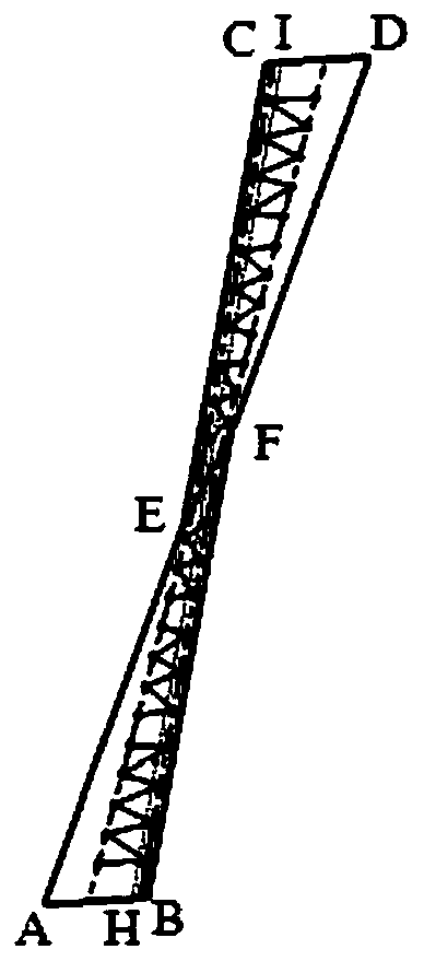
[0022] Embodiment 2: The difference between this embodiment and Embodiment 1 is that the special-shaped foil gasket described in step 3 is composed of a different quadrilateral EFBA and a different quadrilateral EFDC, and the different quadrilateral EFBA and the different quadrilateral EFDC are along the center of the EF midpoint. Symmetrical, the weld crease coincides with EF, and FB and EC are guaranteed to be parallel to the weld of the metal outer joint. Others are the same as the first embodiment.

specific Embodiment approach 3

[0023] Embodiment 3: The difference between this embodiment and Embodiment 1 or 2 is that the special-shaped foil gasket in step 3 is made of 304 stainless steel. Others are the same as those in Embodiment 1 or 2.


PUM

PropertyMeasurementUnit
tensile strengthaaaaaaaaaa
thicknessaaaaaaaaaa
thicknessaaaaaaaaaa

Abstract

The invention belongs to the field of precise connection of variable-type ultra-thin metal structures, and particularly relates to a side part welding method of a variable-type ultra-thin structure, in particular to a welding method of the side parts of a metal inner layer, a flexible middle layer and a metal outer layer of the variable-type ultra-thin structure. The welding method aims to solve the problem that the side parts of the metal layer, the flexible layer and the metal layer of the variable-type ultra-thin structure cannot be reliably connected. The welding method comprises the steps: first, the metal inner layer is welded; second, the flexible middle layer is wrapped; and third, the metal outer layer is welded. The welding method has the advantages that the tensile strength reaches 600 MPa, and the maximum allowable inflatable air pressure difference of the welded structure is 1 atm. The welding method is mainly used for welding the side parts of the metal inner layer, the flexible middle layer and the metal outer layer of the variable-type ultra-thin structure.

Description

technical field [0001] The invention belongs to the field of precise connection of variable ultra-thin metal structures, in particular to a side welding method of variable ultra-thin structures. Background technique [0002] The characteristic of the deformable structure is that it can be folded into a small-volume state during transportation, and can be unfolded into a large-volume state during use. No damage to the structure occurs during folding and unfolding. Therefore, the space required for transportation can be effectively reduced, thereby saving transportation costs. It is widely used in aerospace, construction and other fields. [0003] The most common variable structure is a single layer, and the multilayer structure is formed by combining the single layer structure in the form of metal layer-flexible layer-metal layer. This combined multi-layer structure has the following three advantages: 1. Compared with the single-layer structure, the rigidity is increased, ...

Claims


Application Information

Patent Timeline
Patent Type & Authority Applications(China)
IPC IPC(8): B23K26/21B23K31/02B23K37/04
CPCB23K31/02B23K37/04B23K26/21
Inventor 聂大明卢文涛帅可董晨辉李隆睿刘江淮
Owner 浙江普兴电子科技有限公司
Why Eureka
Try Eureka